What's new
Pinball info

Register a free account today to become a member! Once signed in, you'll be able to participate on this site by adding your own topics and posts, as well as connect with other members through your own private inbox!

PinBot pruebas y tribulaciones españolas :-(

Crewey

Site Supporter
Joined
Dec 19, 2021
Messages
1,323
Location
CH4
Trying to source the problem of two 'red' flashers on my Pin-Bot (spanish v) not working, started off trying to just fix his left eye not working and now I can't remember if the red flashers worked before I fiddled.
Being a muppet initially I didn't realise there was both #89 and #1251 incandescent so was randomly moving the bayonets between each other to work out if it was a socket or bulb issue.

My noob question is if I've put an #89 in a #1251 socket and vice versa #1251 in a #89 socket, what is the worst damage I could have done please?

Also what's with the #86 bulbs .... I'm positive Williams wouldn't have used these on the og PB build so why did the spanish put them in the pop-bumpers. They just fall out of the sockets and do not sit correctly :mad:

thanks
 
#1251 - 28v 6W
#89 - 13v 7.5w

Cent see much that swapping would cause other than not working (if you put a #89 in a #1251 socket though it would probably blow)... Both are single base, so meaning that no likeyhood of shorting two different feeds out...
 
Bear in mind that Pin-Bot (the u.s. version anyway) followed Williams practice at the time of wiring flashbulbs in series. Each of those in the light-bar topper, f'r instance, is paired (as I recall) with one on the playfield, apart from its companion in the topper. Either having failed results in that circuit not illuminating. And watch out for/check the flashbulb resistor boards scattered around (if the Spanish didn't precede Williams by grouping them together). Each circuit has a low value resistor in series to raise the circuit resistance, and a higher value 'warming' resistor to allow the bulbs a small current at all times, prolonging their life, hopefully. If they're the same as Williams boards, each caters for two flashbulb circuits. Looking back at the For Sale thread, they aren't exactly like Williams ones, but there are boards with high wattage resistors on.

As for Jet bumper lamps, I think Pin-Bot was Williams final game with bayonet lamps in them, typically No. 44.
 
Last edited:
Crewey,

Just out of curiosity, does your Spanish edition Pin-Bot have an oddity that was present on the u.s. version?

It arises from the solenoid assignments - one of the eye-socket flashbulb circuits (the right, I think) drives from a 'special' solenoid drive. To use it, the hardware has to enable the special solenoids, and thus also the flipper relay.

During the attract mode, the displays give instructions, such as 'fill chest to open visor', followed by opening it. Then it's 'lock my eye-balls', with the eject hole flashbulbs alternating left-right. The bumpers, slingshots and flipper relay are all enabled while this happens, though any activity resulting, such as a flipper operating, results in them shutting off again. I found out when a bumper nipped me, while cleaning the playfield with attract mode running.
 
Last edited:
Crewey,

Just out of curiosity, does your Spanish edition Pin-Bot have an oddity that was present on the u.s. version?

It arises from the solenoid assignments - one of the eye-socket flashbulb circuits (the right, I think) drives from a 'special' solenoid drive. To use it, the hardware has to enable the special solenoids, and flipper relay.

During the attract mode, the displays give instructions, such as 'fill chest to open visor', followed by opening it. Then it's 'lock my eye-balls', with the eject hole flashbulbs alternating left-right. The bumpers, slingshots and flipper relay are all enabled while this happens, though any activity resulting, such as a flipper operating, result in it shutting off again. I found out when a bumper nipped me, while cleaning the playfield with attract mode running.
Hi Jay, I've not noticed but will certainly keep a look out and report back. With the language changed to English text, the attract mode instructions are still in German oddly enough.
 
I remember a Cyclone which did that, the attract mode message mentioned 'Dem Zyklon' rather than 'The Cyclone' as its third line. It may be due to the language default jumper on the Cpu board. The early System 11 games had English or German text, and which was used as default depended on the link W 7; boards with it removed (or cut) defaulted to German. With the attract mode message remaining in German, even with English text selected manually.

In that case, the Cyclone had a different machines' Cpu board in, which was a German spec. game, including the instruction card.
 
Last edited:
Hi @Jay Walker El Pinboto has the same oddity as you described, when he was in attract mode lifting his visor I was able to activate a flipper once which then ended the attract mode and disabled the flipper again. Very odd
 
I've some parts arriving for PB tomorrow hopefully so will try to resolve the Flasher issues, while taking the plastics and ramps up.
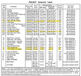
Highlighted below are the flashers failing on test; please can anyone see any continuity between them, that may not simply be bulb or holder related?
Any help appreciated, thank you.

PB.png
 
Williams own arrangements at the time were notorious for broken resistors, with the leads snapping off. Other than that, check all lamps in each circuit. I'm surprised that the location chart for the playfield solenoids isn't any help, e.g. 'Left Playfield Flasher' isn't that helpful on its own, other than by elimination, while a drawing ought to have it pointed out. I have a notion of this circuit (or part of it, anyway) being behind the target bank?

I see it's the left eye-socket at the root of that peculiarity, btw. I'd always recalled it as the right.
 
Last edited:
Williams own arrangements at the time were notorious for broken resistors, with the leads snapping off. Other than that, check all lamps in each circuit. I'm surprised that the location chart for the playfield solenoids isn't any help, e.g. 'Left Playfield Flasher' isn't that helpful on its own, other than by elimination, while a drawing ought to have it pointed out. I have a notion of this circuit (or part of it, anyway) being behind the target bank?

I see it's the left eye-socket at the root of that peculiarity, btw. I'd always recalled it as the right.

Thanks @Jay Walker I'll test the non-working lamps tomorrow, the physical locations are easily locatable (not sure if that's what you meant or the manual pages?)
Good to know about the broken resistor issue, and the eye sockets thank you :thumbs:
 
I meant the page in the manual, where a drawing of the playfield has solenoid and flashbulb locations marked out. Except it doesn't point out the flashbulbs.
 
Top red flashers now working, bulb holder to the left was exiting the bottom, pinched it in and is now holding.
Slingshot flasher bulbs, holders are both ok as they are gently pulsing a faint light during test but not flashing. Will locate the resistors to check them. Eye socket bulbs are working ok
 
A resistor has definitely disconnected below the left sling shot, will try and resolve without pestering @AlanJ as he's already helping me with the lack of background music 😆
 
Bulbs all spot on & Pinbot fully working as of today. Thanks to @AlanJ for providing hours of free support in troubleshooting and not telling me to eff'offski.
The legend @myPinballs for sorting the pesky broken traces on the MPU, so El Pinboto finally has his 80s synth soundzzz jamming.
I already loved the theme, game, mad space FX and creepy callouts but with the music all working it's such a wonderful beast.
 
😭 Received an Xpin from PH @philpalmer, fast delivery, super straight forward install....... fml

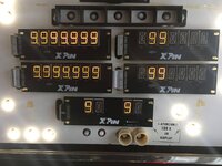
Players 1 & 3 are correct, Player 2 & 4 only work in the segments shown below and the Credit/Match display is showing in the wrong segment.
I have swapped around the displays and the issue is consistent as below. Ribbon cables 1&2, credit match are original, ribbon cables 3 & 4 are new from Xpin so it shouldn't be dodgy ribbons.
If I remove the ribbon cable from the CPU the whole display goes blank (a thread on pinside says this is incorrect apparently 😏)

Anyone out there before have any experience of Xpin's doing something similar to this before I email their support ?
Could it be a quirk of the Spanish connection (for example the Comet LED kit I bought was totally wrong compared with Williams, they swapped them for me without any hassle)
Dodgy Xpin driver board? As Jim @myPinballs has just given the CPU a once over I can't imagine it'd be a problem on that end.

(The original display works fine except Player 2 is gassing out big time and credit digit 2 is overbright)
Any advice would be appreciated..... now back to Robocop issue 😒


IMG-0030.JPG
 
Last edited:
😭 Received an Xpin from PH @philpalmer, fast delivery, super straight forward install....... fml

Players 1 & 3 are correct, Player 2 & 4 only work in the segments shown below and the Credit/Match display is showing in the wrong segment.
I have swapped around the displays and the issue is consistent as below. Ribbon cables 1&2, credit match are original, ribbon cables 3 & 4 are new from Xpin so it shouldn't be dodgy ribbons.
If I remove the ribbon cable from the CPU the whole display goes blank (a thread on pinside says this is incorrect apparently 😏)

Anyone out there before have any experience of Xpin's doing something similar to this before I email their support ?
Could it be a quirk of the Spanish connection (for example the Comet LED kit I bought was totally wrong compared with Williams, they swapped them for me without any hassle)
Dodgy Xpin driver board? As Jim @myPinballs has just given the CPU a once over I can't imagine it'd be a problem on that end.

(The original display works fine except Player 2 is gassing out big time and credit digit 2 is overbright)
Any advice would be appreciated..... now back to Robocop issue 😒


View attachment 173348
I would do a quick sanity check on the ribbon connections. Make sure correct orientation for all ie pin1 red stripe to pin1 etc and also that non are 1 pin out or 1 row out. Easy to do with ribbon cable plugs
 
I would do a quick sanity check on the ribbon connections. Make sure correct orientation for all ie pin1 red stripe to pin1 etc and also that non are 1 pin out or 1 row out. Easy to do with ribbon cable plugs
Cheers Jim, the Xpin sockets have notches on them. I'll see which ones I can reverse :thumbs:

Untitled.png
 
Ahhh haaa .... ribbon cables seem fine switched them every which way the notches allow and the issue is consistent @myPinballs
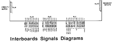
However... wiggling 4J2 or 4J3 connectors on the display side briefly enable's missing digital segments on Players 2&4 nothing changes on the credit match issue.
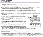
The connectors on these maybe the problem as they have a nubbin below the key which could I think might be stopping them connect flush to the board 🤔

Display
Display side.png

CPU
CPU side.png
 
😭popped out the key blocker on each connector and didn't improve a thing.
Have tried every variation of every ribbon cable possible.
From putting light finger pressure on the Xpin display board around the area of U2 all digits have displayed data at the same time on a couple of occcasions.
My conclusion from this is the data is getting to the Xpin, which eliminates any cable issue's or this PB's roots. Therefore a trace or chip problem exists?

I will contact PH @philpalmer tomorrow and ask if he wants to assist with me only receiving this yesterday, or if I need to go direct to Xpin.
Cheers all
 
Back
Top Bottom