Just looked at the schematic - C30 is a good shout. Cap C30 and R55 and R56 look to provide a voltage delay. Maybe they are stopping reset line? If you have another 22uF cap parallel it up.What do you think is it ok if I measure beetveen c30 + and tp ground 2.8v value?
Pinball info
You are using an out of date browser. It may not display this or other websites correctly.
You should upgrade or use an alternative browser.
You should upgrade or use an alternative browser.
Pinbot does not want to boot
- Thread starter Balazs
- Start date
I replaced it already but nothing changed.
Also replaced all the transistors in the reset section because there was some oxidation. And I checked the resistors as well.
The 10 ohms resistor when I measured itsomtime showed 17 ohms somtime 12ohms.
I also jumpered the reset pin to ground
Also replaced all the transistors in the reset section because there was some oxidation. And I checked the resistors as well.
The 10 ohms resistor when I measured itsomtime showed 17 ohms somtime 12ohms.
I also jumpered the reset pin to ground
Mate, you have me beat. I will have think but not sure what to check next.
Someone on here more experienced with SYS 11 is bound to have some ideas.
Someone on here more experienced with SYS 11 is bound to have some ideas.
A quick Google just found this:
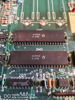
Check the 74LS244 chips at U11 and U13.
If either of these two chips is bad, the game will never boot. Check both of these chips using your multimeter with the game off. You should get a reading between .4 and .6 volts. If you get a short (zero) reading, replace that chip.
Check the 74LS244 chips at U11 and U13.
If either of these two chips is bad, the game will never boot. Check both of these chips using your multimeter with the game off. You should get a reading between .4 and .6 volts. If you get a short (zero) reading, replace that chip.
Last edited:
I would disconnect every board apart from the CPU and ignore that for now. Until you have a good, booting CPU it is not worth going any further with other boards.
Take a photo around the batteries..... or where they used to be......
Take a photo around the batteries..... or where they used to be......
Ok thank you for your helpI would disconnect every board apart from the CPU and ignore that for now. Until you have a good, booting CPU it is not worth going any further with other boards.
Take a photo around the batteries..... or where they used to be......
Ok thank you for your help
Attachments
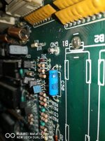
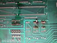
Battery corrosion like that I normally categorise as beyond economical repair as in it's better to buy a replacement board than spend many, many hours repairing the corrosion. There is a massive amount of repair work to do.
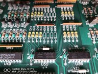
You've got battery damage to those PIAs.
Not just the PIAs, almost every picture has damage showing.
- Joined
- Jul 21, 2011
- Messages
- 3,867
Yes, hence all needs cleaning.Not just the PIAs, almost every picture has damage showing.
We probably should have started with some pictures yesterday! I agree with @Moonraker that is BER, I would look for a new boardI ve got like this.
I know the battery leaking can cause problem.
But the board looks not to bad for me.
Ok thank you very muchWe probably should have started with some pictures yesterday! I agree with @Moonraker that is BER, I would look for a new board
Ok thank you for your helpBattery corrosion like that I normally categorise as beyond economical repair as in it's better to buy a replacement board than spend many, many hours repairing the corrosion. There is a massive amount of repair work to do.
Not yet sorry I will able to check the cpu and the roms soon.@Balazs did you get this fixed in the end?
You know I dont want to throw the board out. I like to repair things this is my hobby so the time what I spend on it does not really matter.Not yet sorry I will able to check the cpu and the roms soon.
You know I dont want to throw the board out. I like to repair things this is my hobby so the time what I spend on it does not really matter.
Very noble and full of good intentions.
Best start with have you a professional solder station that has de-soldering capabilities ? If not best find one, fine tip temperature controlled to 400 deg.
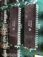
Next best source ALL the components shown in the last two pictures you provided above. 6821's are becoming increasingly difficult to find. Work out how much it will cost you.
Then you need to remove all affected components, where the solder has turned green, white or dark grey or indeed any other colour other than nice shiny silver.
Then you need to scrub the tracks to remove the worst, then use a neturalising solution and repair any damaged tracks then start re-populating and soldering the replacement components.
I would continuity test each leg soldered to avoid problematic fault finding once the board has been repopulated.
Thanks I did similar before on a wpc mpu which had battery damege and I could repair it still working for 1.5 years. I neatralized the board and changed all the components which was affected.Very noble and full of good intentions.
Best start with have you a professional solder station that has de-soldering capabilities ? If not best find one, fine tip temperature controlled to 400 deg.
Next best source ALL the components shown in the last two pictures you provided above. 6821's are becoming increasingly difficult to find. Work out how much it will cost you.
Then you need to remove all affected components, where the solder has turned green, white or dark grey or indeed any other colour other than nice shiny silver.
Then you need to scrub the tracks to remove the worst, then use a neturalising solution and repair any damaged tracks then start re-populating and soldering the replacement components.
I would continuity test each leg soldered to avoid problematic fault finding once the board has been repopulated.
I already find 6821 it was not a problemand
I have soldering station.