Interesting - I've not seen one of these in the flesh! I'd be curious to see if it would work in a real pin. I'll pm you my contact details Keith
Pinball info
You are using an out of date browser. It may not display this or other websites correctly.
You should upgrade or use an alternative browser.
You should upgrade or use an alternative browser.
Pin2dmd stuck on boot screen 'Bally/williams'
- Thread starter David_Vi
- Start date
Holy thread resurrection!
So I have a problem with a pin2dmd I got last week that looks identical to @David_Vi's .
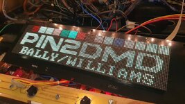
I installed it into my Demo Man (it was 100% connected correctly to the 12v) and it boots to this screen

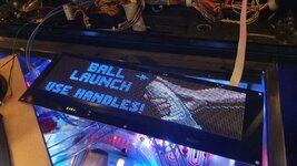
And then this one

where it just sits like this. I have installed the latest firmware with no change. I then swapped it into my IJ and the problem followed it whereas the one out of my IJ worked in DM so I know the files etc are ok on the SD card.

Have I missed some setting in the config menu or is this lightly to be a defective PCB as previously mentioned in this thread?
So I have a problem with a pin2dmd I got last week that looks identical to @David_Vi's .
I installed it into my Demo Man (it was 100% connected correctly to the 12v) and it boots to this screen

And then this one

where it just sits like this. I have installed the latest firmware with no change. I then swapped it into my IJ and the problem followed it whereas the one out of my IJ worked in DM so I know the files etc are ok on the SD card.

Have I missed some setting in the config menu or is this lightly to be a defective PCB as previously mentioned in this thread?
This normally means no data is arriving at the processor on the PIN2DMD. That could be the ribbon cable is in the wrong way around (any easy thing to check).
If there is data coming through the ribbon cable and the ribbon cable is in the right way around then there is possibly an issue getting the data from the connector through to the processor.
First step is try again with the ribbon cable the other way around…
If there is data coming through the ribbon cable and the ribbon cable is in the right way around then there is possibly an issue getting the data from the connector through to the processor.
First step is try again with the ribbon cable the other way around…
Thanks for responding 
Its defo the right way round (pin 1 to pin 1), I have them in 2 other B/W games and its the same orientation. I did try turning it round earlier just in case but the result was the same.
I tried plugging the original dmd back in and it was fine, also the pin2dmd from my IJ works.
Its defo the right way round (pin 1 to pin 1), I have them in 2 other B/W games and its the same orientation. I did try turning it round earlier just in case but the result was the same.
I tried plugging the original dmd back in and it was fine, also the pin2dmd from my IJ works.
I had a similar issue a while ago. I put it into setting mode, reset the display to default setting and then re selected device to Bally / Williams and then ensure you save the setting, that worked for meThanks for responding
Its defo the right way round (pin 1 to pin 1), I have them in 2 other B/W games and its the same orientation. I did try turning it round earlier just in case but the result was the same.
I tried plugging the original dmd back in and it was fine, also the pin2dmd from my IJ works.
Sounds like a defect on the board I’m afraid.
From memory there is some logic that takes the signal from the connector and presents it to the processor. Looks like the processor is fine - which could make it a viable repair.
From memory there is some logic that takes the signal from the connector and presents it to the processor. Looks like the processor is fine - which could make it a viable repair.
Thanks, I will give this one more go but I have tried resetting it previouslyI had a similar issue a while ago. I put it into setting mode, reset the display to default setting and then re selected device to Bally / Williams and then ensure you save the setting, that worked for me
Thanks, it's what I suspected. Any idea who would be able to have a look at it for me?Sounds like a defect on the board I’m afraid.
From memory there is some logic that takes the signal from the connector and presents it to the processor. Looks like the processor is fine - which could make it a viable repair.
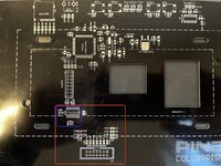
The schematic for the board is here: EVO128X32
There are only a few resistors from each pin of the input connector (j2) (all inside the red rectangle), before going straight to the processor - except one pin with (pin 9) which drives the DMD Clock IC (IC1 - 74LS123D - inside the blue rectangle).
My guess would be one of 3 suggestions:
1 the DMD Clock circuit has failed - try replacing IC1
2 may have a dry joint on IC1
3 one or more of the tracks has been damaged around the red rectangle area. Power does need to come into IC1 so check for a damaged track that could be feeding IC1 - pin 16, which is on the back of the board - track heading off at 10 o'clock to the + (red) power connector of your DMD panel.
Hope all that makes sense?
Mike

Last edited:
I guess it could also be one of those passives which failed? Should be easy to test those resistors and caps with a DMM.
Absolutely - they can get knocked when not handled carefully. If any of those failed or are pulled from the board would cause your problem. So as @Fubar says - check the resistors and capacitors around that area also (including R20 and C35 sitting just above the red rectangle).I guess it could also be one of those passives which failed? Should be easy to test those resistors and caps with a DMM.
Dude, got the board back today working perfectly, thank you, I would be completely stuck without your intervention 

For those following the thread - the problem turned out to be a faulty LS123 (IC1).Dude, got the board back today working perfectly, thank you, I would be completely stuck without your intervention
If you ever have this problem and you’re absolutely sure the ribbon cable is good (and in the right way around) -
You can test the ribbon cable input (J2) of your board to confirm the processor is sensing any input from each of the pins.
You do this by putting the board into input test mode (hold down button 1, press reset, then let go of button 1… cycle through to TEST INPUT, and press button 2 to enter test mode).
Then - from left to right, connect the top pin with its corresponding bottom pin on the input connector (J2) - a short wire or even better a jumper connector is all you need for this. The DMD screen will confirm if the state changes (1,3,5,7,11 and 13). If it doesn’t change and you’re sure the pins are connected you have a damaged pin, track or resistor for that pin
Pin 9 goes through IC1, that pin does not get sensed by test input mode.
If all other pins test ok - it’s a very high possibility that IC1 is broken and needs to be replaced.
Glad it’s all sorted.
