What's new
Pinball info

Register a free account today to become a member! Once signed in, you'll be able to participate on this site by adding your own topics and posts, as well as connect with other members through your own private inbox!

Pcb repair advice

domlouis

Registered
10 Years
Joined
May 28, 2014
Messages
1,681
Location
Derby
Hello
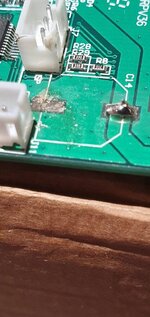
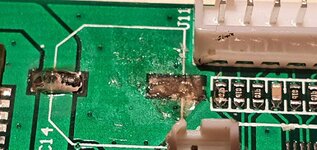
So I have messed up trying to lift a surface mounted capacitor of a pcb. The pad that's part of the pcb came up with the capacitor leg. I then tried to see if I could solder to what was left on the board but made more mess than anything else. See the picture.
Is there any way I could recover the situation or is it new board time? The board is from an intercom. It was faulty. It is expensive to replace and none of the intercom people who I spoke to would consider repairing boards. So I had to try. But I failed 😔. Help.
 

Attachments

  • 16324278127856510403449545019966.jpg
    16324278127856510403449545019966.jpg
    74.5 KB · Views: 45
Thank you for the advice.
I can't see the trace on top so how do i find the termination point?
About removing the lacquer, any specific advice on how to do it?
Thanks
 
I don’t think I phrased it well but where does the trace lead to? Maybe use a multimeter to check but just use a jumper wire straight there, bypassing the lifted pad.

or Alan’s method sounds good if you got a sharp blade.
 
It looks like the pad was part of that huge area of copper that surrounds it I cant tell 100% from your picture if they are connected or not, but if they are one and the same, then just use any other part of that copper,
If you are not sure, post a close up pic for us to look at

scrape off the green with a knife or screwdriver
 
Is that any better? Taken from a different angle. I can't see any track that gets to that pad. And the pad doesn't look connected to anything either. So i am thinking it must be subsurface.
 

Attachments

  • 16324302827845921271431560535099.jpg
    16324302827845921271431560535099.jpg
    119.1 KB · Views: 33
You should be able to see something if you have a strong light source behind it. Find that trace that did link it, carefully scrape off the green with a blade as described above. Then it's just a case of tie-ing it together.
 
The pad that has lifted was connected to the surrounding large copper area by a narrow track at the centre of each narrow side of the rectangle. It is done like that so that it is thermally isolated from the larger area of copper and will solder OK in the reflow solder process, otherwise it would need much more heat to get a good joint. You can scrape off some of the green solder resist either side of the missing pad and solder a link wire across to then solder the capacitor terminal too. Or you might be able to move the capacitor sideways (upwards in the first photo) by the width of the pad and remove the green solder resist on both tracks as long as the pad on the right-hand side of the new capacitor (as seen in the first photo) isn't too large or it will bridge the right-hand track to the larger copper area. The green solder resist is fairly easy to scrape off but needs to be completely removed in the area you want to solder.
 
Keith,
I think I have managed to repair it.
There were another two capacitors to remove. One went well and the other not so well. See photo. I think i can scratch a bit of green solder resist at the bottom of the bottom pad as this seems to be where the track is at the bottom. I am a bit confused about the top one. Any idea where I can scratch some green stuff and solder to?
Thanks
Dom
 

Attachments

  • 20210925_223132.jpg
    20210925_223132.jpg
    96.1 KB · Views: 16
Keith,
I think I have managed to repair it.
There were another two capacitors to remove. One went well and the other not so well. See photo. I think i can scratch a bit of green solder resist at the bottom of the bottom pad as this seems to be where the track is at the bottom. I am a bit confused about the top one. Any idea where I can scratch some green stuff and solder to?
Thanks
Dom
I think you are right about the bottom of the bottom pad. As far as I can see the top pad was connected to the larger area of copper surrounding it, similar to the previous one.
 
Those are electrolytic caps so the pad that came off will be negative and going to ground. The ground will likely be a ground plane (ie the entire board not covered by traces). Usually if pads have no traces they tend to lift during removal. That could have been the case with this one although being connected to the plane it should have held.

As other have explained, just try scrape back the solder resist to get the the ground plane and solder to that, or if not possible put a trace to ground from that leg.
 
Last edited:
So I replaced the three capacitors, I reconnected it all and tried it and I have lost some functionality.
The board is part of an intercom and carries a Sim card. The phone element of the board isn't working (the keypad element on the other side works well which is an improvement).
Is there any way of testing a capacitor once installed?
Thanks
Dom
 
Hi Dom,
A bit hard to say without more knowledge of the device and the logic that lead to replacing those capacitors in the first place. Some test meters can test capacitors but generally aren't very reliable at testing them in circuit. There are specialist testers that can do it but they are quite pricey. The best you can do is to try and test that the new capacitors are all reliably connected to the pcb at both ends. The negative ends are generally all connected to ground so you should measure a low resistance between the negative side of each new capacitor and each of the other new ones. The positive side you will have to try and make a resistance check between the solder pad on the capacitor and another component on the same copper track. If you don't have a low resistance connection on any one of them then re-check your repair to that connection.
Good luck
Keith
 
Back
Top Bottom