What's new
Pinball info

Register a free account today to become a member! Once signed in, you'll be able to participate on this site by adding your own topics and posts, as well as connect with other members through your own private inbox!

One for the boffins

stumblor

Site Supporter
Joined
Sep 16, 2018
Messages
3,719
Location
London UK
Alias
Davey Price
I have a bit of a head scratcher.

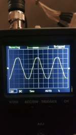
I'm looking at the GI AC outputs of the transformer of my WPC machine, the ones that connect to J115 and power the games GI and should be around 6.3VAC. Looking at the wave through my (shamefully cheap) scope, I can see the wave is inbalanced.
1615318003059.png

You can see that it has slightly more amplitude on the positive side that the negative.

Now here's where it gets weird. If we don't send up the middle pin from that transformer connector (which goes to J115-1 and is tagged as reference ground in the schematics), the wave looks the same, lopsided. However, if we do send it up, the wave looks like it should.
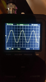
1615318170567.png

Even top and bottom.

Pinfest beers waiting for anyone who can explain to me whats going on!
 
Ah, that yellow and white wire that goes to the ground side of the board.
I spent a lot of time trying to work that yellow and white wire out, without a scope, whilst checking the transformer of BSD at the weekend. It connect to the board on the earth side. What does it feed it to cause the phase to be smoothed out?

On BSD all the wires were spliced on J115 and the other end for the GI, J120, J121 and J119 which are fed by this.
 
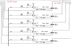
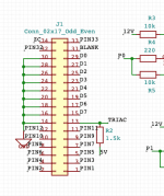
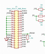
That's what I can't really work out. The only thing that seems to interact with the negative part of the wave is the Triacs, but I thought these effectively acted as switches so not sure what part they're playing.

1615321668239.png

What I'm trying to do is power a GI OCD and have these lines active at the same time (using a splitter).

Without the GND REF pin, it all works and can be shared, but the lopsided AC wave doesn't play nicely with the GI.
With the center pin fixes the lopsidedness, but blows the fuse on the GI OCD. I've no idea why.
 
Last edited:
First of all, i would say that for all intents and purposes, electrically they're the same waveform.

But there is a slight difference...

You're measuring an AC wave but with your scope set to DC mode. This means that you see the AC PLUS any DC offset what might exist, which I think does very slightly in your first wave.

This shifts the whole wave up, relative to ground, a few units of voltage.

Connecting the center ground will probably remove this offset, but i need get schematics in front of me to check.

Explain exactly what you're trying to do again? Power a mod board?
 
Had a quick look at your Williams triac GI circuit and its a bit of a nasty one :)
They are pretty much just cutting down on parts to achieve DC controlled AC switching.

For the triacs to be switch by the DC side they have to have reference to the DC side.
Their solution is to gnd one side of the 6.3v coil to DC gnd.
Rough stuff :)
 
Thanks for the insight guys will post a full response in a bit
 
Had a quick look at your Williams triac GI circuit and its a bit of a nasty one :)
They are pretty much just cutting down on parts to achieve DC controlled AC switching.

For the triacs to be switch by the DC side they have to have reference to the DC side.
Their solution is to gnd one side of the 6.3v coil to DC gnd.
Rough stuff :)

I suspect its this grounding that is causing the amps to ramp up on the GI OCD and the fuse to blow.

Explain exactly what you're trying to do again? Power a mod board?

This is the background..

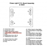
CFTBL has a chase board that runs the ramp and whirlpool lights, which uses two of the AC GI lines to power the lights. The lights need to be AC so that LED bulbs can be inserted in either direction. When using a GI OCD or an Afterglow board in the game, these chase lights stop working - because those boards convert all the AC GI into PWM DC.

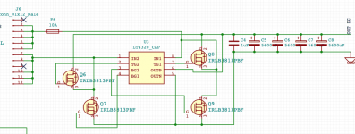
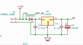
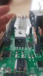
Both the GI OCD and the Afterglow are powered using the J120 connector, it converts the AC power into 5V DC using a combination of a mosfet diode bridge (which reduces voltage drop), and then a more typical 7805 to regulate the resulting voltage (9V or so I believe).

Here's what that part of those boards looks like.

1615369274287.png
The diode bridge

1615369291120.png
The regulator

What I'm attempting to do is to create a splitter at the transformer that sends some of the 6.3VAC lines to the chase board, and some to power the GI OCD/Afterglow.

  • When the GI OCD/Afterglow not connected, all the bulbs run at full brightness.
  • With the GI OCD/Afterglow connected, the bulbs facing the opposite direction (ie those picking up the -ve signal) run at reduced brightness.
Not sure how the mosfet bridge, and/or the ground reference pin all relate to each other to cause the issue, or how to resolve it. Keeping those 6.3VAC separated (ie not sharing the same lines between both) doesn't help either so they must be connected in ways I don't know about.
 
I always love the way they used the transformer tap for Thermionic Valve heaters. Transformer manufacturers could just pull out the old specs.

David
 
I suspect its this grounding that is causing the amps to ramp up on the GI OCD and the fuse to blow.


This is the background..

CFTBL has a chase board that runs the ramp and whirlpool lights, which uses two of the AC GI lines to power the lights. The lights need to be AC so that LED bulbs can be inserted in either direction. When using a GI OCD or an Afterglow board in the game, these chase lights stop working - because those boards convert all the AC GI into PWM DC.

Both the GI OCD and the Afterglow are powered using the J120 connector, it converts the AC power into 5V DC using a combination of a mosfet diode bridge (which reduces voltage drop), and then a more typical 7805 to regulate the resulting voltage (9V or so I believe).

Here's what that part of those boards looks like.

View attachment 134420
The diode bridge

View attachment 134421
The regulator

What I'm attempting to do is to create a splitter at the transformer that sends some of the 6.3VAC lines to the chase board, and some to power the GI OCD/Afterglow.

  • When the GI OCD/Afterglow not connected, all the bulbs run at full brightness.
  • With the GI OCD/Afterglow connected, the bulbs facing the opposite direction (ie those picking up the -ve signal) run at reduced brightness.
Not sure how the mosfet bridge, and/or the ground reference pin all relate to each other to cause the issue, or how to resolve it. Keeping those 6.3VAC separated (ie not sharing the same lines between both) doesn't help either so they must be connected in ways I don't know about.
10A fuse???? Linear regulator these days?

David
 
Does your J6 connect to ? the triac switched output?

As long as your not connecting your new circuits GI DC gnd to the pinballs gnd you should be OK.
 
An 'ideal' diode bridge to minimise voltage drop followed by a linear voltage regulator...........


David
 
Does your J6 connect to ? the triac switched output?

As long as your not connecting your new circuits GI DC gnd to the pinballs gnd you should be OK.

No J6 connects directly to the 6.3VAC transformer outputs.

As soon as that's connected, it affects the chase lights (also connected to the 6.3VAC outputs).
 
But is your new GIDC gnd connected to the pinball DC gnd? as you cant do that in this instance.
 
You mean J120-1 (GND REF) ? No, it's not connected.
If you look at the WPC drawings its connected to the transformers coils I think.
So J120-1 and J120-7,8,10,11,12 etc are all connected together.

So again are you connecting your new GIDC circuits gnd to the pinballs power driver boards gnd?

Or is your GIDC gnd isolated from all the rest?
 
If you look at the WPC drawings its connected to the transformers coils I think.
So J120-1 and J120-7,8,10,11,12 etc are all connected together.

So again are you connecting your new GIDC circuits gnd to the pinballs gnd?

The chase board is connected to pinball ground via its J1 connector

The Afterglow and GI OCD board (I think) create their own ground via the diode bridge.

interestingly, the issue doesn't occur if the ribbon cable isn't connected to the GI OCD/Afterglow, could it be because this new generated GND is being sent back?

1615374381457.png
 
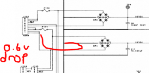
In the normal game the Game ground becomes referenced for AC via a diode forward voltage drop in the bridge. With the 'ideal' bridge the Ground reference has no voltage drop so the two grounds are different which becomes a problem when those two grounds are connected somewhere.

David
 
1615375808574.png1615375994899.png

So if the OCD 'Gnd' is connected to game 'Gnd' there will be problems on the same transformer tap.

David
 
Removing ground from the ribbon cable fixes the problem - but now the GI fading is all over the place, obviously because it no longer has a correct ground reference o_O
 
You could ground via a diode but grounds must not touch. Why use the 'ideal' diode bridge then use a linear regulator that then has to dissipate more heat as a result makes no sense at all.

David
 
You'd have to take that up with herg @ LEDOCD mate :p

Since i'm going for compatibility, I'm a bit stuck as to what i can and can't do - ie, creating two separated ground planes on the board isn't an option. The GI OCD does have a USB and FTDI header though, maybe the right option is to power to board that way instead of using the ideal diode bridge at all.
Why not raise it with Herg, you won't be the only one with this problem.

David
 
I think your making all this overcomplicated by looking at other areas of the Wiliams circuit
Nothing to do with the other bridge rectifiers.

The easiest way to sort out your problem @stumblor is to just use half wave rectification on the 6.3vac and smooth it to **** and add a reg.

Your complicated Fet bridge rectifier circuit is OTT and obviuosly causing issues on how your using it.
 
Thanks @Vimtoman but remeber... the FET bridge is not my design :p That is part of the GI OCD and Afterglow design, so I have no control with how that's working (or not working) - unless I bypass it somehow altogether, which is why I was thinking about trying to use the FTDI header to power it instead.

Half wave rectification and smoothing - you're talking about how to generate a 5V regulated output from AC though yeah?
 
Had no idea it was not your design.

OK so your getting conflict with GI OCD and afterglow products with this chase board?
 
Back
Top Bottom