What's new
Pinball info

Register a free account today to become a member! Once signed in, you'll be able to participate on this site by adding your own topics and posts, as well as connect with other members through your own private inbox!

In Progress Node board repair

Fubar

Site Supporter
Joined
Feb 5, 2020
Messages
1,711
Location
Cambridge, UK
Alias
Thomas
In this thread I will share my adventures repairing broken node boards. There's not a lot of information out there as I guess they don't break that much and/or the people who fix them don't share their findings. Now I'm by no means an electronics super-guru so all comments are very welcome. :thumbs:

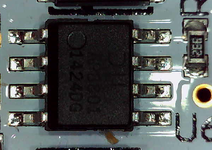
To start with, we have a CPU board on which the backbox LEDs don't work: at startup, they illuminate briefly before cutting out. This board was kindly entrusted to me by @Sam C who has a video of the problem in another thread so check that out if you want. Based on one related pinside thread, it could be the LED driver chip (AP8801SG-13) but I'd like to confirm that before starting shotgun replacements.

I don't have a spike2 machine in the house however I do have another CPU board which works and will be useful to compare to.

We can get the schematic from Stern's website for this part of the board:
2023-03-21-194149_1378x310_scrot.png
2023-03-21-220037_448x158_scrot.png

Some interesting points to note:
  • I can't find the top row of LEDs (D26..D53) on the actual board, it looks like they must be an alternative part - or possibly I'm just a bit thick?
  • The driving BL_PWM signal comes straight from the node bridge MCU at PIO0_17.
  • The comment in the top right mentions R64 but I can't seem to find it??
  • The driver chip is running at its max recommended operating voltage (48V), only 2V away from its absolute max rating. Hopefully there are no big spikes on that rail...

Now since the LEDs do light up briefly we know they all work. The input and output to the chain are easily accessible on CN15 so let's probe that.

PXL_20230321_192852703.jpg

For the keen readers who opened the driver's datasheet, we are effectively probing its SET (blue) and SW (red) outputs (the latter being behind a couple passives). At startup we can see the initial flash:

20230321-0001_bad-startup.png

And afterwards nothing really happens. Let's compare it to our good board...

20230321-0004_good-startup.png

...which eventually reaches this steady state where the LEDs are quite dimmed:

20230321-0003_good-steady.png

Even non-technical readers at this point will note a marked difference :)

Let's now probe the input (BL_PWM, MCU output) as a sanity check -- note that this board otherwise plays fine so the node bridge processor must be functional -- both test subjects indeed look the same so no need to double the picture:

20230321-0006_bad_blpwm.png

and then after Q4 the inverting MOSFET we have CTRL (driver input), which is slightly different between bad (left) and good (right):
20230321-0007_bad_ctrl.png 20230321-0008_good_ctrl.png

In the BAD case, the falling edge is not as sharp and takes a bit longer to settle. Worth noting that the driver accepts both PWM signals as well as analog voltage variations to control the LED intensity. However I don't see how the above could explain the behaviour we're seeing...


At this point I think it's worth replacing the suspect driver chip, which has conveniently appeared in stock at Farnell. :) Whilst waiting for that, the next step is to write a little program to manually control the backbox lights, as waiting several minutes for the game to boot each time is proving tiresome. Watch this space!
 
Last edited:
the next step is to write a little program to manually control the backbox lights, as waiting several minutes for the game to boot each time is proving tiresome.
Since I've spent quite a few evenings over the past couple years hacking spike stuff, this didn't take very long at all.

Surprising result: it works perfectly on the GOOD board - I can set the LEDs to various intensities from retina-burning to comfortable (note to self: next time wear sunglasses when dialing it in...) 😎

However on the BAD board nothing happens (well OK they are broken) not even the initial flash which is triggered by the game. Not sure why this is, as I'm using the exact same intensity value as the game does (and the program works on the other board)...

C:
int main(int argc, char** argv)
{
  unsigned intensity = 0x2000;
  if (argc > 1)
    intensity = strtol(argv[1], NULL, 10);
  if (intensity > 0xffff)
    intensity = 0x2000;

  if (NODEBUS_Restart())
    return 1;

  printf("Set backbox intensity to: 0x%04x\n", intensity);
  NODEBUS_SetBackboxLight(intensity);

  return 0;
}

Anyway now it's back to waiting for parts - think I'll go and play some pinball :clap:
 
Hi,
I hope you don’t mind me chiming in. I don’t know your skill level so please forgive me if I’m talking about stuff you already know.

The circuit snippet you show is a pretty straightforward constant current driver circuit designed to drive LEDs. For anyone who doesn’t know, LEDs are current driven devices – not voltage driven. Here’s an explanation of what that means.

You can (within reason) stick whatever voltage you like across an LED and drive it by limiting the amount of current that flows through the LED. A simple way of doing this is to use a resistor in series with the LED. Note that the LEDs are connected in series so the same amount of current flows through all of them.

1679480324030.png

In the above example, I have assumed that we are using the same LEDs as shown in the Stern manual (Cree XQDAWT-00-0000-00000HDE5). These have a forward voltage (Vf) of 3.1V and operate at a suggested forward current (If) of 350mA.
If we chose the series resistor method, we would calculate the series resistor value as follows.
  • Total voltage dropped across the LEDs = Vf x number of LEDs = 3.1V x 10 = 31V.
  • Required forward current Vf = 350mA (0.35A).
  • Resistor value = (Supply voltage – LED voltage) / Required current = (48-31)/0.35 = 48.57 Ohm.
  • We would choose a 51 Ohm resistor in this case as it is the closest available value to 48.57.
Although this is simple and would work, it is very inefficient. A lot of power would be dissipated by the series resistor – 5.95 Watts. The power consumed by the LEDs is 10.85 Watts, a total of 16.8 Watts. This means that the circuit is only about 64% efficient – (Power through the LEDs / Total power) x 100 = (10.85 / 16.8) x 100 = 64.58%. This is pretty bad and would require a sizeable, wire wound series resistor rated at 10 Watts.

A much better way of doing this is to use a current limiting device instead – which is what the Stern engineers did. They used a dedicated chip designed to limit the total current flowing through the string of LEDs. The circuit now looks something like this.

1679480360284.png

They don’t need a series resistor to dissipate lots of power. Instead, this chip only allows the amount of current programmed via RSet (R50 in your circuit diagram) to flow through the circuit. This is much more efficient and allows the designer to vary the brightness of the string of LEDs by varying the frequency and duration of the signal applied to the CTRL input of the chip. This is known as pulse width modulation – PWM.

According to the Stern notes, they have selected a 1.2 Ohm resistor for R50 – meaning the chip will limit the current through the LED string to 337mA – which is slightly lower than the 350mA that the LEDs are rated for.

Looking at the traces in your post, I can see that the CPU drives the CTRL input about every 40 microseconds (0.00004 seconds). This means the PWM frequency is around 25KHz (1/0.00004 = 25000) – which is pretty fast.

The system varies the brightness of the LEDs by varying the duty cycle. This is done by driving the CTRL signal high for a percentage of the time. For example, if the CTRL is driven every 40 us and held high for 10us, the positive duty cycle will be 25% (i.e., driven high for 10 out of 40us). If CTRL is held high for 30us, the positive duty cycle will be 75%. The positive duty cycle equates to the brightness of the string of LEDs. When CTRL is driven high, current will flow through the LEDs and cause them to light for that percentage of the time period.

As an aside, you noticed that the falling edge of the MOSFET output was a little more sluggish on the faulty board than on a good one. It is usual for this to happen and is dependant on what the MOSFET is driving into. The only way to get MOSFET outputs to ‘snap’ high and low quickly is to actively drive them in both directions (using another MOSFET). A good place to get more information is to look at MOSFETs being used to drive motors or in switch mode power supplies. Just for kicks, here’s my scope showing a single MOSFET driving high powered LEDs directly – you can see the sluggish falling edge too. Having said that, the fact that you see a difference between a good and bad board suggests that your theory about a faulty AP8801 chip is probably correct.

1679480396358.png

You mentioned that Stern didn’t fit LEDs D26-D53. There are 2 strings of LEDs – D26-D53 and D40-D49. The rules for a parallel circuit (in this case 2 strings of LEDs in parallel) state that the total current in a circuit is equal to the sum of currents flowing through each parallel branch. The circuit is designed to let 337mA flow in total. If we assume that each string of LEDs were identical, that means that only around 170mA would flow through each string – reducing the potential brightness of each string by 50%. This can be useful though – it would mean that the same overall amount of light could be spread across a wider physical area which might look better in some circumstances.

Right then, enough of the theory, what do I think is going on here?

One problem is that your scope is displaying voltage - not current. You won’t see obvious highs and lows like you do with the PWM signal and MOSFET outputs. To see what is going on with the output of this chip, you’d need to display current instead. You can do this with a current probe for your scope (very expensive) or using a resistor (very cheap).

It looks like the PWM input to the MOSFET is fine, the MOSFET looks like it is switching happily so the input stage looks OK. To me, this means that either the current limiting chip itself is faulty (which is what you are thinking) or one of the discrete components around the chip is faulty (most likely the inductor at L12 or possibly Schottky rectifier D8).

My money is on a faulty AP8801 chip as you suspect – but I’ve been wrong before. I’m looking forward to hearing if the replacement chip worked for you.
 
Last edited:
Hi,
I hope you don’t mind me chiming in. I don’t know your skill level so please forgive me if I’m talking about stuff you already know.

The circuit snippet you show is a pretty straightforward constant current driver circuit designed to drive LEDs. For anyone who doesn’t know, LEDs are current driven devices – not voltage driven. Here’s an explanation of what that means.

You can (within reason) stick whatever voltage you like across an LED and drive it by limiting the amount of current that flows through the LED. A simple way of doing this is to use a resistor in series with the LED. Note that the LEDs are connected in series so the same amount of current flows through all of them.

View attachment 197008

In the above example, I have assumed that we are using the same LEDs as shown in the Stern manual (Cree XQDAWT-00-0000-00000HDE5). These have a forward voltage (Vf) of 3.1V and operate at a suggested forward current (If) of 350mA.
If we chose the series resistor method, we would calculate the series resistor value as follows.
  • Total voltage dropped across the LEDs = Vf x number of LEDs = 3.1V x 10 = 31V.
  • Required forward current Vf = 350mA (0.35A).
  • Resistor value = (Supply voltage – LED voltage) / Required current = (48-31)/0.35 = 48.57 Ohm.
  • We would choose a 51 Ohm resistor in this case as it is the closest available value to 48.57.
Although this is simple and would work, it is very inefficient. A lot of power would be dissipated by the series resistor – 5.95 Watts. The power consumed by the LEDs is 10.85 Watts, a total of 16.8 Watts. This means that the circuit is only about 64% efficient – (Power through the LEDs / Total power) x 100 = (10.85 / 16.8) x 100 = 64.58%. This is pretty bad and would require a sizeable, wire wound series resistor rated at 10 Watts.

A much better way of doing this is to use a current limiting device instead – which is what the Stern engineers did. They used a dedicated chip designed to limit the total current flowing through the string of LEDs. The circuit now looks something like this.

View attachment 197009

They don’t need a series resistor to dissipate lots of power. Instead, this chip only allows the amount of current programmed via RSet (R50 in your circuit diagram) to flow through the circuit. This is much more efficient and allows the designer to vary the brightness of the string of LEDs by varying the frequency and duration of the signal applied to the CTRL input of the chip. This is known as pulse width modulation – PWM.

According to the Stern notes, they have selected a 1.2 Ohm resistor for R50 – meaning the chip will limit the current through the LED string to 337mA – which is slightly lower than the 350mA that the LEDs are rated for.

Looking at the traces in your post, I can see that the CPU drives the CTRL input about every 40 microseconds (0.00004 seconds). This means the PWM frequency is around 25KHz (1/0.00004 = 25000) – which is pretty fast.

The system varies the brightness of the LEDs by varying the duty cycle. This is done by driving the CTRL signal high for a percentage of the time. For example, if the CTRL is driven every 40 us and held high for 10us, the positive duty cycle will be 25% (i.e., driven high for 10 out of 40us). If CTRL is held high for 30us, the positive duty cycle will be 75%. The positive duty cycle equates to the brightness of the string of LEDs. When CTRL is driven high, current will flow through the LEDs and cause them to light for that percentage of the time period.

As an aside, you noticed that the falling edge of the MOSFET output was a little more sluggish on the faulty board than on a good one. It is usual for this to happen and is dependant on what the MOSFET is driving into. The only way to get MOSFET outputs to ‘snap’ high and low quickly is to actively drive them in both directions (using another MOSFET). A good place to get more information is to look at MOSFETs being used to drive motors or in switch mode power supplies. Just for kicks, here’s my scope showing a single MOSFET driving high powered LEDs directly – you can see the sluggish falling edge too. Having said that, the fact that you see a difference between a good and bad board suggests that your theory about a faulty AP8801 chip is probably correct.

View attachment 197010

You mentioned that Stern didn’t fit LEDs D26-D53. There are 2 strings of LEDs – D26-D53 and D40-D49. The rules for a parallel circuit (in this case 2 strings of LEDs in parallel) state that the total current in a circuit is equal to the sum of currents flowing through each parallel branch. The circuit is designed to let 337mA flow in total. If we assume that each string of LEDs were identical, that means that only around 170mA would flow through each string – reducing the potential brightness of each string by 50%. This can be useful though – it would mean that the same overall amount of light could be spread across a wider physical area which might look better in some circumstances.

Right then, enough of the theory, what do I think is going on here?

One problem is that your scope is displaying voltage - not current. You won’t see obvious highs and lows like you do with the PWM signal and MOSFET outputs. To see what is going on with the output of this chip, you’d need to display current instead. You can do this with a current probe for your scope (very expensive) or using a resistor (very cheap).

It looks like the PWM input to the MOSFET is fine, the MOSFET looks like it is switching happily so the input stage looks OK. To me, this means that either the current limiting chip itself is faulty (which is what you are thinking) or one of the discrete components around the chip is faulty (most likely the inductor at L12 or possibly Schottky rectifier D8).

My money is on a faulty AP8801 chip as you suspect – but I’ve been wrong before. I’m looking forward to hearing if the replacement chip worked for you.
Bit more on measuring current here:
Measuring Current with a scope
 
@Ragnar1057 thank you so much for taking the time to write all that down. As I said at the start all comments are very welcome, and even if some bits are known to me they could be useful to others. For the record my background is in embedded software so my expertise falls squarely in the digital domain.

Probing current is a good idea I hadn't thought about, and is conveniently possible here thanks to CN15. I don't have a current probe but could easily hack a shunt into there. Will give that a go tonight...
 
Code:
The most convenient way to access the board is via the built-in Ethernet port.
This is the RJ45 jack located on the top side of the board (as opposed to the 3
RJ45 jacks on the bottom which connect to the nodes' RS-485 bus). To install a
SSH server on the box, do the following:

  1. Edit /etc/network/interfaces to configure eth0 appropriately (google it).
  2. Copy dropbear and dropbearkey into /usr/local/bin (you can get them from:
      https://github.com/Miraje/dropbear or compile yourself)
  3. Apply the diff below to /etc/rc5.d/S95game
  4. Copy contents of your ~/.ssh/id_rsa.pub to /home/root/.ssh/authorized_keys

--- S95game_orig    2021-01-30 20:05:52.474111782 +0000
+++ S95game    2021-01-30 20:23:49.140021437 +0000
@@ -331,6 +331,17 @@
 #    mount -o remount,ro /
 #fi
 
+
+#================================
+# Network access is cool
+ifup eth0
+if [ ! -f /etc/dropbear/dropbear_rsa_host_key ]; then
+  mount -o remount,rw /
+  dropbearkey -t rsa -f /etc/dropbear/dropbear_rsa_host_key
+  mount -o remount,ro /
+fi
+dropbear
+
 #================================
 # try to launch an application at $GAMES_PATH/game.  this will be a link to the game so
 # that this script doesn't need to change.  redirect stderr messages to log file.


Game menu
---------

The game executable contains a built-in menu which is accessible via stdin once
it is running. It might be possible to get this via the serial console on CN2,
I just don't use it anymore. To access it, once logged in via SSH, restart the
game:

  pkill -9 game
  /games/game

(To stop the game, press Ctrl-Z then run the pkill command again.)

Then press any letter and Enter, you should be greeted by the following:

  commands:
          adj: perform operations on adjustments.
          amp: amp system interface.
          aud: perform operations on audits.
          coil: fire a coil.
          credit: manipulate credits.
          debug: get debug information.
          display: display system interface.
          dsp: DSP interface.
          knocker: perform operations on the knocker.
          le: lamp effect system interface.
          mode: interact with modes.
          node: node diagnostics commands.
          nv: get non-volatile ram info.
          proc: get information about processes.
          red: redemption interface.
          replay: replay interface.
          scene_cache: scene cache system interface.
          score: manipulate player scores.
          sound: sound system interface.
          textsafe: show text safe region.
          video_display: video display system interface.

Type a command group to get more help about. Some example commands:

  mode status
  mode start N
  debug errors list
  display request N
  le request N
  sound request N


Cross-compiling
---------------

From a Ubuntu 20.04 installation, a compatible toolchain can be easily installed:

  sudo yum install gcc-arm-linux-gnueabihf

Something i've wanted to tinker with for a while but i don't have any boards. I kinda like the sound of the diagnostics command for the node board.
 
Something i've wanted to tinker with for a while but i don't have any boards. I kinda like the sound of the diagnostics command for the node board.

Yes actually I wrote that text long ago and you can see the ethernet cable in the photo above. I now have a 1-liner script which installs remote access on a SD card.

That debug menu was unfortunately removed from game executables around the time IC came along. Of course it's still possible to use an older game image for this stuff, if you have one. I didn't find anything terribly useful in terms of diagnostics though - many of the juicier commands didn't seem to do anything...
 
  • Like
Reactions: Arv
@Ragnar1057 thank you so much for taking the time to write all that down. As I said at the start all comments are very welcome, and even if some bits are known to me they could be useful to others. For the record my background is in embedded software so my expertise falls squarely in the digital domain.

Probing current is a good idea I hadn't thought about, and is conveniently possible here thanks to CN15. I don't have a current probe but could easily hack a shunt into there. Will give that a go tonight...
You're welcome mate.
Embedded software eh? I might hassle you for help at some point. I'm working on a microcontroller based pinball machine project at the moment so I may need to pick your brains from time to time;)

I figured you'd know what you're talking about - not many people have a Picoscope...
 
Right, so tonight I thought I'd have a go at measuring current. First problem is I don't have a suitable resistor, however I did find an old potentiometer which I wound down to 1Ohm (edit: this didn't work - suspect the pot is buggered). Fired it up and... now it works?! The owner of the board had told me that the failure had been getting sporadic, and that it used to be possible to resurrect the lighting by varying the intensity in the game's settings menu. Still, I'd not done any of that and now I could switch it on and off using my test program, at varying levels of intensity, all working just fine. Running the game executable also yields satisfactory results.

Edit: actually the owner has confirmed that the failure was indeed sporadic. Which makes it hard to verify any attempted fix...

Now, one thing I did do was try fitting a test clip on the AP8801SG chip. These allow for easier probing of them tiny pins.
2406243-40.jpg


Now I thought perhaps that action had somehow squeezed the chip's legs and made good a previously faulty contact?? Now I could just try reflowing all its legs, but how would I know if the fix will stand the test of time? 🤔

I took a few pictures of it with my crappy inspection camera and couldn't really see any obviously failed solder joints. But then again the image quality is not amazing and solder rarely flows over the leg with modern manufacturing techniques... Think I might bring it to the office tomorrow where we have a proper microscope.
 

Attachments

  • 2023-03-22-201711_903x641_scrot.png
    2023-03-22-201711_903x641_scrot.png
    233.5 KB · Views: 15
  • 2023-03-22-201743_826x650_scrot.png
    2023-03-22-201743_826x650_scrot.png
    218.3 KB · Views: 148
  • 2023-03-22-201804_843x604_scrot.png
    2023-03-22-201804_843x604_scrot.png
    203.4 KB · Views: 15
Last edited:
Right so after a bit of thinking (and a long interruption from the wife), the plan is to replace the driver chip anyway and send it back to the owner until it fails again (or not!)

Before that I thought I'd try this new test clip to see if I could capture the whole picture. Maybe it will look different even though the fault isn't present? (Side note: couldn't measure current as I don't have a current probe nor a suitable resistor for use as a shunt.)

Did someone call the spaghetti monster ?!
PXL_20230322_213721749.jpg

BLUE: CTRL -- RED: VIN -- GREEN: SET -- YELLOW: SW
20230322-0002_ctrl-vin-set-sw_startup.png 20230322-0001_ctrl-vin-set-sw.png

...and let's compare to our good board (startup then dimmed)...

20230322-0003_good_startup.png 20230322-0004_good_steady.png

Only real difference being the falling edge from the FET being crisper as mentioned previously. We'll check this again after replacing the driver and see if it will match the good board. 🧐

The difference in the SW trace compared to the OP is marked. One difference this time is that the ground clip of the probe was on the chip's leg, whereas previously it was on a board header further away. Guess I should invest in a current probe after all! ...
 
Last edited:
Oh, how we love intermittent faults…

As expected, you’ve been thorough and methodical with your troubleshooting – but sometimes it gets to a point where you just have to make an educated guess.

There are so many possibilities: Maybe there is a bad joint on one of the pins, or the chip is being awkward and reaching the end of its life (Vin is very close to its absolute maximum rating as you already noted). Even temperature can be a factor. I’ve fallen foul of this in the past with one of my designs when using an X7R ceramic capacitor instead of a C0G type – one of the supply rails wouldn’t start up when first unboxed after shipping, but would be fine if left at room temperature for a few minutes. Perhaps the Moon isn’t aligned favourably with Venus😊.

Again, all the inputs to the chip look reasonable so I would still suspect one or more of the 3 components I mentioned earlier - and I think your plan to change the chip is a good one. I think it would be a false economy to just resolder the chip as you wouldn’t really know if that made a difference or not. As you say, how long do you test before you convince yourself that you’ve made a difference.

Just curious, are the connections the same as when you first tested this (I can't see the first photo in your message)? Sometimes, connecting the ground of the scope to different locations can effect return paths and allow the chip to start.
 
Oh, how we love intermittent faults…

As expected, you’ve been thorough and methodical with your troubleshooting – but sometimes it gets to a point where you just have to make an educated guess.
Agreed - it's just the engineer in me hates the uncertainty! At work if I can't prove a fix is correct it doesn't get past team review :)

Just curious, are the connections the same as when you first tested this (I can't see the first photo in your message)? Sometimes, connecting the ground of the scope to different locations can effect return paths and allow the chip to start.
Pic should be fixed now. The probe grounds are indeed different for logistical reasons, however it started working before I put probes on. Temperature might be a factor... I could try putting the board in the fridge for a while! :D
 
Now for the bit where most people rightfully don't want to venture... SMD component replacement. On pinside there is a vocal minority waxing lyrical about the good old days of through-hole technology, and how surface-mount is just a planned obsolescence thingy :rolleyes: I would recommend the SMD soldering videos on the EEVblog channel on youtube which really helped me when I started with this stuff.

In all honesty surface mount work isn't that hard if you have the right tools. Forgot to include on the picture is a flux pen - very important! But otherwise a soldering iron with a fine tip and some fine solder and braid are all that's needed.

PXL_20230323_214813286.jpg

Removing the component is the annoying bit. I don't have a reflow station (aka hot air gun), so my preferred method is a mix of desoldering braid and good ol' fashioned butchery aka break its legz!

Once the chip is off the board (and in a sorry state...), clean the pads up with desoldering braid and isopropyl alcohol.

2023-03-23-221252_864x597_scrot.png

To place the component, tin a single pad in a corner, then place the component and tack it into place. Once happy with the placement, solder the opposite corner to lock it in place.

2023-03-23-221532_697x685_scrot.png

After that just solder down all the legs, clean with alcohol, and inspect for any defects.

Yeah, I put way too much solder on, I know... 🫣

2023-03-23-221924_699x696_scrot.png 2023-03-23-222015_709x487_scrot.png


Only one thing left to do now - power it up and address a prayer to our deity of choice! 🙏 And... bad news, the fault remains the same :( Got it to light up once when set to full intensity, then nothing working again.

So it's back to the drawing board! My next suspect is the diode D8 but now it's time for bed 😴
 
Hmm, that's disappointing. I had high hopes that it was a chip problem - but it's not the first time I've been wrong;).
Let's hope D8 fixes it...
 
I don't have a reflow station (aka hot air gun)
If you have the spare cash I'd recommend the KSGER 858D Hot Air Rework Station - treat yourself, it's a big help.

Helps diagnose problems removing and replacing parts 1 at a time without trashing them in the process. great review of it here

I also got the KSGER T12 V3.1S Soldering Station to go with it - nice and compact, reliable and very flexible with the interchangeable tips
 
If you have the spare cash I'd recommend the KSGER 858D Hot Air Rework Station - treat yourself, it's a big help.
Yeah I've been toying with the idea of a rework station for a while, might be time... Not too keen on these cheap clones though as in my experience you never know what you're gonna get so they end up costing more in the long run, and also ignore the most basic safety measures (like grounding the case for example). One has to severely cut corners to reach a $50 price point on this and it's not the kind of business I personally want to be supporting anymore.

Already got a weller pu81 soldering iron which I'm very happy with, didn't break the bank either.
 
Taking a break from the temperamental lights, our next subject on the bench is a cabinet node board. Apparently it was showing a fault on the game's display - got pretty much no history / info on this one.

Now there is a helpful table in the schematics:
2023-03-25-200834_1089x185_scrot.png

Feeding it 48V lights D19 as expected. I need to make some cabling to allow powering both it and the CPU from my bench supply, but in the meanwhile I power the CPU with 48V and then bridge the 12V rail over with some jumpers.

PXL_20230325_201301173.jpg

With that D1 seems to be in he 10Hz 50% regime and after a few minutes switches to 1Hz 90%, i.e. it's not getting data from the CPU. This tells us that the LPC1313 is booting and running stern's firmware.

Hmmm... what does the game have to say? Since I don't have a suitable pin here I need another way to get to the display output. A quick guddle through the code shows that the game helpfully responds to the SPIKE_PRIMARY environment variable allowing the main video feed to be switched from CN6 to CN10, the HDMI connector, which I can easily wire up to my PC's screen.

PXL_20230325_201424633.jpg

Nodes 8 & 9 are excusable but I'm pretty sure node 1 should be the cabinet! The CPU board is functional (well apart from the LED problem above), and the node board is known damaged, so the next place to start looking is the comms circuit which is on the next page in the schematic:

2023-03-25-203220_1216x827_scrot.png

First thing which comes to mind is probe 5VI, so I look for a test point on the board and notice this:

(Should have started with a visual inspection!!)

2023-03-25-203729_943x711_scrot.png

Oh dear!! U17 is a NAND gate which controls the direction of the RS-485 transceiver. Yeah that ain't gonna work!

Trying to clean it up with some alcohol half the legs snap off. Way to go you oaf!! 😡 Good news is thankfully no lifted traces. Bad news is they're still very gunky and the spacing is tiny :(

2023-03-25-210534_1067x931_scrot.png

Now it's off to the kitchen to get some vinegar and a pan of sorts...
 
Ooh, nasty.
I don't often see a logic IC fail like that - I'd normally expect the isolator to self terminate. The surrounding damage makes me wonder if something corrosive has landed on it.
I'd say you've probably found the cause of the comms error;).

I didn't realise Stern use RS485 for Comms. I'm working on a project at the moment that requires 120 ohm impedance comms cables (CAN-FD). I used Belden 9841 RS485 cable which is a bit pricey. Can you get me any info on the type of cable Stern use for Comms so I can see if it will be cheaper than the type I'm using now? I could have used CAT5e but that is 100 Ohm.

I bet Stern use CAT5e:D.
 
My suspicion is that someone spilt some drink on the game - that board is normally located near the front of the cab.

Yes they use off-the-shelf network cables. CN13 in the schematic above is a RJ45 port.
 
Wow there’s a hell of a lot of great info here.
I took the simplistic approach.
Spike 1 system and reported my issue somewhere on here last week.
I’m a total novice by the way…
Got myself a rework station and bought 4 x
U33 chip
LED drive chip AP8801SG-13
My logic:
- before replacing the LED drive chip get some heat on it to see if it sorts issue. I heated the chip with flux @380 degrees Celsius with hot air gun.
- put the board back in place

Seems to have fixed issue

I would replace chip if further issues but wondering if a cold solder issue.

My onboard LED lights were flickering then went dead

I’ve had my Kiss pin operational with no issues for 24 hours.
Hope this helps.

38D2E852-157E-4417-AF22-C55E4E1FCF0D.jpegCCD0EF06-58E6-45E5-81D8-E0CF222C5C85.jpeg857CDA98-A67C-4C99-9705-C75983E3A2B8.jpeg
 
Last edited:
@Sako-TRG glad an easier fix worked for you, please let us know if that cured the problem permanently or if it ever comes back. That's the hard things with these complex systems there's so many "what if" scenarios...

There are no silly questions :) Yes I did put the replacement chip on the right way round.
 
Now for the bit where most people rightfully don't want to venture... SMD component replacement. On pinside there is a vocal minority waxing lyrical about the good old days of through-hole technology, and how surface-mount is just a planned obsolescence thingy :rolleyes: I would recommend the SMD soldering videos on the EEVblog channel on youtube which really helped me when I started with this stuff.

In all honesty surface mount work isn't that hard if you have the right tools. Forgot to include on the picture is a flux pen - very important! But otherwise a soldering iron with a fine tip and some fine solder and braid are all that's needed.

View attachment 197175

Removing the component is the annoying bit. I don't have a reflow station (aka hot air gun), so my preferred method is a mix of desoldering braid and good ol' fashioned butchery aka break its legz!

Once the chip is off the board (and in a sorry state...), clean the pads up with desoldering braid and isopropyl alcohol.

View attachment 197176

To place the component, tin a single pad in a corner, then place the component and tack it into place. Once happy with the placement, solder the opposite corner to lock it in place.

View attachment 197177

After that just solder down all the legs, clean with alcohol, and inspect for any defects.

Yeah, I put way too much solder on, I know... 🫣

View attachment 197178 View attachment 197179


Only one thing left to do now - power it up and address a prayer to our deity of choice! 🙏 And... bad news, the fault remains the same :( Got it to light up once when set to full intensity, then nothing working again.

So it's back to the drawing board! My next suspect is the diode D8 but now it's time for bed 😴

great thread Thomas
I was looking at the picture on the right and it looks perhaps like R49 (3K3) is maybe not soldered on the left-pad in particular. This is the pull down for the 'ctrl' input
cheers Bob
 
great thread Thomas
I was looking at the picture on the right and it looks perhaps like R49 (3K3) is maybe not soldered on the left-pad in particular. This is the pull down for the 'ctrl' input
cheers Bob
Thanks for the kind words Bob. Agree it looks suspicious on that photo. Just took a look from another angle and I think it's ok although hard to be certain - this is where my setup shows its limits in terms of image quality... I'll reflow it anyway as doesn't cost much to do.

2023-03-26-144930_1920x1200_scrot.png
 
Spent some time on that cabinet node board yesterday... Good news is it works! Bad news is I'm rather not proud of my work - looks terrible :(

The green gunk flaked off quite easily when scraped with a sharp blade, I was able to clean the IC all around and everything on the PCB, however a couple of the pads didn't survive. Definitely a bit of a learning experience here and most of my tools are too big to work on this 0.65mm pitch sucker! Used some copper braid and wire to replace the missing pads - again that's too big being a whole millimeter wide :rolleyes:

So yeah no close-ups this time as I'm too ashamed 🙈 Here's the whole thing working again though:

IMG_4153.JPG

IMG_4151.JPG

Next step will be to apply some protection over all them delicate bodges, and then some easier work convincing the software that the missing PDB isn't an issue really.
 
Well, I replaced D8 today. Cleaned it up, powered it back on, and... It lit up! Quite happy with that of course :)

IMG_4154.JPG

After a little while however the driver chip started hissing between pins 2 & 3 (which are GND & NC) so I quickly powered it off. (My PSU is limited to 250mA which is the lowest it can go - still at 48V that's a bit of power.) Yes I did solder the replacement diode on the right way! 😅

Now when I power it on the driver chip quickly gets very hot so clearly it's buggered! 🤬 Have given in and ordered a reflow station as I'm not confident I can remove that chip a second time without lifting a trace.

1679950246106.png
 
So I heeded Mike's advice and got myself a rework station - fabulous tool how did I ever cope without it? 🤔 With that I replaced the infamous driver U6 and the inductor L12. A quick test shows the LEDs flickering - progress?

Upon closer inspection I notice that some soot seems to be coming from underneath C90. Multimeter shows weird readings across it - could it be our culprit?!

2023-04-03-203732_958x793_scrot.png

Once again praising my latest addition to the bench I get it off the board, test it standalone with my multimeter and indeed it's a dead short!! 🤬

Trying to clean up the pad it's not pretty... That via is GND and on the left across the chasm is 48VDC. Too close for comfort!

2023-04-03-204104_951x767_scrot.png

Looking back at a previous picture in this thread, I wonder if it was a cold joint from the factory which eventually wreaked chaos... In this pic from post #10 it clearly looks like the solder has not come up the side of the part just under the C90 marking:

2023-03-22-201743_826x650_scrot-png.197077


Lesson learned: spend more time inspecting the board before reaching for your soldering iron! Back to the matter at hand though... Sadly a couple pad lifted from underneath the driver and things are looking a bit grim to be honest 🙈 I cut the NC leg as its pad was absent anyway (no connected to anything so was the first to bugger off), and also bridged the two SW outputs together as one of them has a dubious pad.

2023-04-03-204726_1078x714_scrot.png

Deciding to do a bit more analysis before applying power, I now notice that R50 isn't reading right. Take that off the board, measure it, and...it's reading 1000x its nominal value (yes I had to double-check that: it reads 1.2kohms and should be 1.1ohms as per the schematic and its 1R10 markings). I'm guessing it got side burns from the capacitor and/or driver. Speaking of which, that chip is now reading 150ohms between its SET and GND pins (1 & 2) which definitely ain't right. This is with R50 off the board and nothing on CN15 so definitely fried - that's going to have to come off a 3rd time 🤦‍♂️

By now I'm obviously feeling a bit depressed about this issue and also feeling bad that I've caused some damage to a board which isn't mine. Thankfully it's not created more issues than were present when I got the board but still not a good look... I might need to invest in an ultrasonic bath next as not sure I'm going to get all the soot out of the smaller gaps in-between components. My wife hasn't even noticed the rework station yet!

Next step would be to replace the driver chip again - I'm starting to wonder if it wouldn't be better to get everything off the board in that area, give things a good clean-up, and replace every part of the LED circuit in one go. That would also help with the whole cleaning up part. The alternative is to give up, remove D7 to ensure the circuit is powered off, and illuminate the backbox with an external LED strip. Right now I need a break though!
 
Glad to read you’re enjoying your new rework tool… they are a game changer as you say.

ultrasonic cleaner I have - but rarely use - if you lived closer you could borrow it no problem… I got it from a group buy on here… maybe someone closer to you has one they would loan you when needed? Not sure it’s a tool everyone needs on the bench (quite big for your average hobbyist workbench too - mine is currently in a mates storage unit!).

Interesting reading your progress… all good experience. Looking forward to the next instalment
 
Back
Top Bottom