What's new
Pinball info

Register a free account today to become a member! Once signed in, you'll be able to participate on this site by adding your own topics and posts, as well as connect with other members through your own private inbox!

New to Pinball Info and looking for direction.

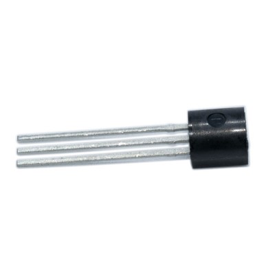
OK. They fit exactly as the present ones are fitted. The middle leg of the TIP49 is probably cut off as it make its connection through the bolt in the tab.
Once fitted then unplug CN5 before powering up and measure the voltage between the screw head at the bottom of the board (black probe) and Pin 8 of CN5 (red probe) looking for 160 - 175V DC before it is safe to power off and reconnect CN5 to try the game again. Don't forget to check CN10 and CN11 on the CPU board for correct alignment and no bent pins too. Good luck, you are making good progress and no doubt learning a lot too.
 
Also check Pin 10 of CN5 with the red probe to make sure that your -5V is in the range -4.8 to -5.2V after RG2 has been replaced.
 
How's it going with this @Thehipster ?
Funny you should ask. Last part arrived today and I have refitted the new parts to the board. All of the reads into CN1 are perfect. All of the reads into CN5 are perfect EXCEPT pin 8 which reads only 1 VDC. I am away until Sunday from tomorrow and I was going to leave it until I got back. I am thinking (but I am hoping that @Zaccaria Keith will correct me if I am wrong) but it must be something on the board preventing the 170v getting to the CN5.
Oh there was a bent pin at the very bottom of CN11 now straightened.
 
Check in the following order when you have time and report each result:

Check the orientation of the new components TR1, TR2, TR3 on the board and check carefully for any solder bridging between the tracks around the 170V section of the board where these parts are fitted.

1) check that 1A fuse F1 is intact
2) check the DC voltage between each end of R1 (red lead to left end) - should be about 235V ish
3) Check the DC voltage between the top end of R3 and a mounting screw at the bottom of the board (red lead to R3) - should be about170V
 
Sounds like you're getting close to actually being able to play the game at least. It will all be worth it, cracking game. Such a pain that this happened.
 
Check in the following order when you have time and report each result:

Check the orientation of the new components TR1, TR2, TR3 on the board and check carefully for any solder bridging between the tracks around the 170V section of the board where these parts are fitted.

1) check that 1A fuse F1 is intact
2) check the DC voltage between each end of R1 (red lead to left end) - should be about 235V ish
3) Check the DC voltage between the top end of R3 and a mounting screw at the bottom of the board (red lead to R3) - should be about170V
R1 reads 220vdc. R3 read 180 at first and now 1.2vdc
I checked the soldering carefully before I mounted the board also.
I was thinking that the R3 resistor might have taken the brunt of the R1 burnout?
 
Last edited:
If the reading on R3 starts at 180 and then drops to 1.2V then the overcurrent trip circuit is operating. I assume you still have CN5 unplugged at this point?

Turn off all power and measure the resistance of R5 (should be 2.2ohms) and R4 (should be 100ohms or sometimes 220ohms but you might get a different reading on this if you try the meter probes each way round)
I am getting 4.2 and 102 and yes i have not plugged in CN5
 
Ok. R5 is a bit high but meters sometimes struggle to measure low resistance accurately. Without the displays connected it shouldn't trip even if it is that high. It is possible that the scr is damaged. If you unbolt the board and swing it round you should be able to unsolder the top leg of scr1 and pull that leg out of the joint so it is not connected. Then screw the board back in and test the voltage on cn5 pin 8
 
Ok. R5 is a bit high but meters sometimes struggle to measure low resistance accurately. Without the displays connected it shouldn't trip even if it is that high. It is possible that the scr is damaged. If you unbolt the board and swing it round you should be able to unsolder the top leg of scr1 and pull that leg out of the joint so it is not connected. Then screw the board back in and test the voltage on cn5 pin 8
Keith thanks for the help. I will get onto this next Sunday as I have a 4 am start to drive to sunny Cornwall for a weeks holiday. I will let you know what happens next week
 
Good move. The safest test it to replace it rather than disconnect it, in case there is genuinely a current overload somewhere on the board, even lthough this is unlikely based on the results you have had previously. Just go ahead and fit one of the new ones and then check the voltage at Pin8 of CN5 again (once you come back all refreshed from your holiday!)
 
Good move. The safest test it to replace it rather than disconnect it, in case there is genuinely a current overload somewhere on the board, even lthough this is unlikely based on the results you have had previously. Just go ahead and fit one of the new ones and then check the voltage at Pin8 of CN5 again (once you come back all refreshed from your holiday!)
I got back about an hour ago eager to replace the scr. Pin 8 reads 134vdc . Everything works on the game apart from the display.
Sound, pop bumpers, slingshot, kick back, flippers on the top deck and rollovers are as they should.
Targets all reset after each set is hit.
I am going to leave it until tomorrow as the 7 hour drive back has tired me. Unless you think it is a quick fix.
That voltage is too low for the displays to strike, but it does confirm that the scr was faulty. I will need to take a look at the schematic again and give you some voltages to measure so that we can work out why it isn't up to spec. I'm on holiday this week but should be able to take a look. Was the 134V measured with CN5 connected or disconnected?
 
That voltage is too low for the displays to strike, but it does confirm that the scr was faulty. I will need to take a look at the schematic again and give you some voltages to measure so that we can work out why it isn't up to spec. I'm on holiday this week but should be able to take a look. Was the 134V measured with CN5 connected or disconnected?
CN5 was not connected. I just earthed the black probe and put the red probe on pin 8, taking care not to short it.
 
Ok I will take a look at the circuit tomorrow and suggest some measurements again
When you get time can you send some close up pics of the 170V supply area of the board and also, with the power off and CN5 unplugged, check the actual resistance of R6 to ensure that it is 47R and not 47K
 
When you get time can you send some close up pics of the 170V supply area of the board and also, with the power off and CN5 unplugged, check the actual resistance of R6 to ensure that it is 47R and not 47K
I will do that tomorrow. Do you mean the back of the board?
 
OK thanks for the photos. I can see a number of problems that would explain why the 170V supply is not working:
1) TR2 appears to be fitted incorrectly. The tag on the side of the transistor should line up with the tag shown on the silk-screening on the pcb. The three legs on the transistor are grouped around one half of its base and these would then line up with the three holes in the board which are grouped around one side of the outline on the pcb.
2) I can't see the orientation of TR3 due to the heatsink on it, but the same may be true of that. It is essential that the leads of the transistors are in the correct holes or they will not work correctly and will generally be damaged as a result.
3) TR1 is incorrectly fitted. The metal side of the transistor should be laid flat towards the bottom of the heatsink and held tight to the heatsink by the brass pillar and bolt, with a small smear of the heatsink paste between the heatsink and the metal back of the transistor to improve the transfer of heat - that transistor gets very hot when it is working. The transistor should have the middle lead cut off and the other two go into the two holes on the board and are soldered in. You can see a faint outline on the heatsink of where the old transistor was. I will try to find a photo to show how it should look but I am away on holiday and can't easily take one.
4) R6 appears to be a 47K resistor (47,000 ohms) (Yellow, Purple, Orange) rather than the 47R (47 ohms) which needs to be fitted. The gold stripe at the end of the resistor just shows that the resistance value has a tolerance (accuracy) of 5%, which is fine.

The resistance of R6 being too high may have saved the transistors from damage, although if you have spares left I would use one for TR2 (and TR3 if it is wrongly aligned). The supplier you were linked to before for the replacement of R6 supplies both 47R and 47K resistors so you need to be careful to select the right one.

I'm sure once these problems are corrected you will have a working machine again. Obviously once you have replaced/corrected all of them you should disconnect CN5 and measure the voltage at Pin8 before we go any further. All of the above issues need to be corrected at the same time before trying things again or you may do further damage.
 
Should have said that the correct 47R resistor for R6 will have Yellow, Purple, Black stripes. Again there may be an additional Gold stripe to show 5% tolerance.
 
Back
Top Bottom