What's new
Pinball info

Register a free account today to become a member! Once signed in, you'll be able to participate on this site by adding your own topics and posts, as well as connect with other members through your own private inbox!

New to Pinball Info and looking for direction.

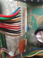
There's a hole under each connector (yellow arrow indicates) and the alignment pin should place in it, unfortunately they're plastic and bend easily (yellow circle showing that it missed the hole). CN5 being a replaced connector, they didn't leave space for the plastic alignment pin hence your problem. Like Keith's picture above that he posted while I wrote this..

Zacc connector.png.
 
The other one to avoid is swapping over CN2 and CN3 on the power board as that blows every bulb in the GI by putting 39V up the 6V bulbs - they don't like it up 'em! I've only done it once with unlabelled connectors but it was just after fitting all new lamps in the machine...
 
Looks like CN1 has an alignment hole to the right too, so that probably isn't an original connector either. That one's easy to line up though as it has an outline of the connector printed on the board. CN5 isn't so easy. It does have those alignment pins on two other connectors.
 
Oh the joys of pinball ownership.
Don't feel bad about it, we have all been there. And the advice you are getting here is the collective learning from all of us (I mean them really, I am still in your camp learning).
Good luck with fixing it. Follow the advice. And you'll get there. And you will feel great about it but the end of the journey.
 
The other one to avoid is swapping over CN2 and CN3 on the power board as that blows every bulb in the GI by putting 39V up the 6V bulbs - they don't like it up 'em! I've only done it once with unlabelled connectors but it was just after fitting all new lamps in the machine...

I've managed something similar blowing 40 playfield controlled bulbs, not sure how as I double checked everything!
 
Looks like CN1 has an alignment hole to the right too, so that probably isn't an original connector either. That one's easy to line up though as it has an outline of the connector printed on the board. CN5 isn't so easy. It does have those alignment pins on two other connectors.

Correct and CN1 being put on incorrectly could really mess things up!
 
I've managed something similar blowing 40 playfield controlled bulbs, not sure how as I double checked everything!
Now you say that I've got a feeling that it might be the controlled lamps that are blown by that crossover - I just remember being very peed off as I swapped out all of the new lamps!
 

Attachments

  • 15988676733495602201688076646330.jpg
    15988676733495602201688076646330.jpg
    64.2 KB · Views: 38
Move CN5 down one pin and you'll see how (also take another photo to confirm that it's been placed correctly). They are a real pain and you've got to be very careful when connecting them as you've found out.
Ive psted a pic. I think it is set correctly now
 
Yes that's right
I see a little dot at the right of the cn1 connector which would suggest an alignment pin. If I move the connector along one to the right leaving a spare pin on the left it would mean a red wire goes into the connector but does not attach to the board. Should all of the pins have a wire on CN1? Incidentally my cn1 red wire read was 184 Vac DDM set at 600vac tested as per Zaccaria-pinball.com pins 1 and 2. The transformer fuse holder is set at 220. I'm out of fuses and the f2 5a has just gone. (I was trying the game without the sound board connected.) Turns out I've lost the 5a transformer fuse too. Very frustrating. Please bear in mind that I am a bit f a novice.
 
CN1 was correctly aligned with all of the pins fitted into all of the holes as the connector doesn't have a spare hole for the alignment pin, so don't move the connector along to the right. Did you measure all of the output voltages on the CN5 connector against the schematic as suggested, before you reconnected it to the rest of the game?
 
CN1 was correctly aligned with all of the pins fitted into all of the holes as the connector doesn't have a spare hole for the alignment pin, so don't move the connector along to the right. Did you measure all of the output voltages on the CN5 connector against the schematic as suggested, before you reconnected it to the rest of the game?
Keith I need to get new fuses and a resistor and then look at this again. I think what I have learned already has been massive. I tested the 10v and 10.5v and they were fine. The 170vac was reading 185vac. The green and white did not have a reading and the brown was 43vac (I may have tested the green and white after I blew the transformer fuse.
Where should I go for the resistor and does it have to be rubberised/plasticised like the one that fried or can it be any 47ohm 3w resistor?
 
Last edited:
Once you have replaced R6 and the fuses, and set the mains transformer to 245V then you need to leave CN5 unplugged and look for the following voltages on the pins of CN5 with the negative lead of the meter connected to ground (e.g. push the probe into one of the screw heads in the bottom corner of the power board):
Note that Pin1 is at the bottom of CN5:
Pin 1 around 40v DC (not critical)
Pin2 Zero
Pin3 Zero
Pin4 +5.6V DC (should be within 5.4 to 5.7V)
Pin5 +5.6V DC (should be within 5.4 to 5.7V)
Pin6 Zero
Pin7 Zero
Pin8 +170V DC (should be between 160Vmin and 175Vmax)
Pin9 Zero
Pin10 Minus 5V DC (should be between -4.8V and -5.2V DC)
Pin11 +5.6V DC (should be within 5.4 to 5.7V)
Pin12 +12V DC (should be within 11V to 13V)

If any of the voltages are not within the ranges given then don't reconnect CN5 - come back here for advice as all of these DC voltages are critical to avoid damage to the circuit boards.
That is a fantatic help. I will update you later in the week.
 
send the board to @myPinballs
I hope you get it sorted, it's any easy mistake to make, i'm sure I have done it a few times!
You can ger the original connectors from https://www.pinballsolutions.eu/ let me know if you need any as I should be making an order soon for my Pinball Champ (they are located in Belgium).
View attachment 118267

You don't need to order from belgium for those amp connectors, i have these connectors to and in many different sizes. They are standard across many pinball games.

ON the CN5 connector front, i would suggest making it 13 pin and putting a polarising key into the pin at the bottom so you cant get it on wrong again. You can get polarising pins for the IDC connector that is currently used or the ones for the AMP type used originally.
 
Last edited:
Yeah I think after this episode it would be a really good idea to replace the connectors on CN5 and CN1 with the ones with locating pins to avoid the chance of anyone else making this same mistake in the future. It looks like I was ridiculously lucky not to make that mistake as obviously so easily done. These Zaccarria's are too rare and hard to find parts for to be taking chances with.
 
I think that wire feeds the motor and bell for the wall of death motorcycle rider on the head of Devil Riders, which that photo was taken from, so probably not used on Pinball Champ.
 
@Zaccaria Keith
So the fuses arrived and I have tested the new ones and replaced the old. Resistor not here yet so I decided to test the VAC on CN1. Results as follows:

Pin 1Wire ColourPin 2Wire ColourVoltage
1Red2Red164VAC
5Yellow6Yellow9VAC
9/10Green/Green11/12White/White6.5VAC
7Blue8Blue43VAC
3Brown4Brown9VAC
 
Those voltages look fine. The yellow pair and brown pair are slightly low but within tolerance. Hopefully you still have CN5 disconnected? You can measure the DC voltages on each pin of CN5 relative to ground as per my earlier post, although you might not see anything on Pin 8 without the resistor replaced. Take care not to short between the pins on CN5 as you make the measurements.
 
Those voltages look fine. The yellow pair and brown pair are slightly low but within tolerance. Hopefully you still have CN5 disconnected? You can measure the DC voltages on each pin of CN5 relative to ground as per my earlier post, although you might not see anything on Pin 8 without the resistor replaced. Take care not to short between the pins on CN5 as you make the measurements.
All voltages/readings are as they should be except the 170 on pin 8 which is zero as you said. When I get the resistor I will let you know what happens. Don't worry I will set the connectors correctly. Should I check the 170 read on pin 8 before connecting cn5?
 
Last edited:
That's great. Repeat the check including pin8 once you have replaced the resistor then as it is important that the 170V is regulating correctly before the displays get connected.
 
That's great. Repeat the check including pin8 once you have replaced the resistor then as it is important that the 170V is regulating correctly before the displays get connected.
I take it the resistor is directional? If so which way is up?
They have arrived so I will be putting the new one on tomorrow.
 
Back
Top Bottom