What's new
Pinball info

Register a free account today to become a member! Once signed in, you'll be able to participate on this site by adding your own topics and posts, as well as connect with other members through your own private inbox!

New to Pinball Info and looking for direction.

Thehipster

Registered
Joined
Aug 29, 2020
Messages
91
Location
Washington UK
Alias
Joe
Hi everyone.

Could anyone tell me where I need to post this:

I have recently acquired a Zaccaria Pinball Champ '82 from a respected member of the group.

Unfortunately it did not travel well and I am trying my best to get it up and running as it should. It worked perfectly before transport and it was expertly delivered by Martin the Man. I thought that I had addressed some of the issues before I blew the F1 fuse by turning it on and off to much I think. I then replaced the fuse with an 8 instead of 1 amp fuse which fried Resistor R6.

This leads me to my first of what will be many cries for help. What resistor do I need to replace the damaged one at R6? I don't normally repair boards myself but my soldering skills are okay.

Thank you.
 
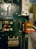
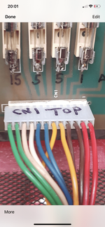
Is anyone able to offer some technical help on this please? It's my old machine and was working faultlessly the night before being sent The head was removed for transit as requested, which obviously is never ideal. Everything was labelled and reattached correctly as far as I can see in photos. It seems that it blew the F4 fuse when switched on. That was replaced but a few other things weren't working, displays and flippers, which I believe is due to the CN5 connector on the power board needing reseating. Unfortunately a few different attempts were made at troubleshooting which has caused further problems including fried resistors on the power board. If anyone could offer some technical assistance to the op that would be really appreciated to get him up and running.
 
Hi everyone.

Could anyone tell me where I need to post this:

I have recently acquired a Zaccaria Pinball Champ '82 from a respected member of the group.

Unfortunately it did not travel well and I am trying my best to get it up and running as it should. It worked perfectly before transport and it was expertly delivered by Martin the Man. I thought that I had addressed some of the issues before I blew the F1 fuse by turning it on and off to much I think. I then replaced the fuse with an 8 instead of 1 amp fuse which fried Resistor R6.

This leads me to my first of what will be many cries for help. What resistor do I need to replace the damaged one at R6? I don't normally repair boards myself but my soldering skills are okay.

Thank you.
send the board to @myPinballs
 
Oh and there was some experimenting with the transformer fuse and confusion over output setting. Op is based in Tyne and Wear if there is anyone local that could take a look?
 
As already mentioned, R6 is 47R 3W. Putting the higher rated fuse in would result in burning out the resistor, but only because there was already something overloading the 170V supply. Check for the power connector on the CPU board being offset by one pin or reversed. Also check the ribbon cable to the displays, and the displays themselves. Disconnect CN5 from the power board and ensure that the 170V supply is OK after replacing R6 as it is possible that TR1 will have blown and the 170V supply will be unregulated which will damage the displays if not repaired.
 
Power cable at CN1 is the right way up, it's labelled. Hard to tell from photos if it's offset.
 
There would need to be a short circuit or at least a severe overload on the 170V supply to burn out R6, so it is imprtant to find out why before reconnecting the load to the 170V supply.
 
That supply just gets tracked around the CPU board from the power connector to the ribbon cable that feeds the displays
 
20200830_200755.jpg
Anc check CN5 on the power board for correct alignment, somtimes the locating keys are missing or bent over and the socket can be put on one pin out
 
If CN5 is displaced upwards by one pin then the 170V supply (normally connected to the yellow wire on Pin8 gets connected to the black wire on Pin 7 which is grounded.
 
Unfortunately that offset puts +5.6V up the -5V input of the sound card and +12V up the +5.6V input of the sound card which doesn't sound like a healthy combination. I think it is important to check all of the power supply card voltages on CN5 of the power board (without the cable connected) once R6 is replaced. If they all match up to the schematic OK, then disconnect the bottom section of CN6 from the sound board before connecting CN5 (correctly!) and test the game without the sound. If all is OK then reconnect the bottom section of CN6 and test to see whether the sound board still functions.
 
I was wondering how there came to be so many dead chips on the sound card of the Devil Riders I am working on - I have a horrible suspicion that I now know what had been done to it previously...
Hopefully you will be luckier, but if not I can repair the sound card.
 
Unfortunately that offset puts +5.6V up the -5V input of the sound card and +12V up the +5.6V input of the sound card which doesn't sound like a healthy combination. I think it is important to check all of the power supply card voltages on CN5 of the power board (without the cable connected) once R6 is replaced. If they all match up to the schematic OK, then disconnect the bottom section of CN6 from the sound board before connecting CN5 (correctly!) and test the game without the sound. If all is OK then reconnect the bottom section of CN6 and test to see whether the sound board still functions.
There was no sound immediately before the resistor fried. I'm guessing a sound card repair will be needed.
 
There wouldn't be any sound whilst the connector was misaligned but you might still be in luck once things are connected correctly. You can test the power board voltages apart from the 170V without replacing R6 and if ok then proceed as noted to test the machine with the sound card disconnected initially. It should play a game but without any displays or sound. You can then try with the sound board connected.
 
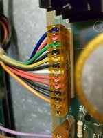
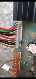
If you look closely at the photo Rob posted above then you will see that the socket has an empty hole at the top and the male on the board has a pin at the bottom that has no scket on it.
 
I am confused as the cn5 connector has 12 wires and 12 pins. How can it be misaligned by one pin.

Move CN5 down one pin and you'll see how (also take another photo to confirm that it's been placed correctly). They are a real pain and you've got to be very careful when connecting them as you've found out.
 
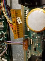
That CN5 socket is not the original one. The original would have had 13 holes and the bottom one would have been fitted with an alignment pin which has to go into a hole in the board below the bottom of the male connector - this makes it impossible to misalign the connector. Look at the photo I posted of a correctly aligned CN5 socket.
 
20200831_103839.jpg
This is what the original connector looks like - you can see the extra way on the socket with an alignment pin fitted
 
Back
Top Bottom