So Nautilus EM has burnt through a fair few coils in the back box at the shows with coils stuck on, no-one noticing and then I have no clue what caused it is as there is always no issue when I check.
So I decided to monitor for stuck coils, originally i was going to add some contacts to the score relays and monitor these, but the drum units can still stick on without the relay operating. So I need to move the monitoring further down the chain.
I cannot just link the coils togethor because this would mean when one coil energised, they would all energise. Unless… I converted the current form AC to DC.
So I designed the first PCB with 5 bridge rectifiers, a current limiting resistor, a diode to reduce back EMF from the coils to a common DC output to trigger a timed relay which then triggered a sounder via N/O contacts.

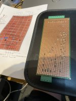
My first design I stupidly scanned the coper side of the board, and did the design on that. Doh!!! So then when it came to relay the design onto the main board everything was backwards… No problem for resistors and diodes (to a degree) but a real bitch for packaged rectifiers that have specific pinout for pos and neg DC not to mention track breaks…
Scrap one Vera board. So I redid the design, properly (took about 12 or so revisions): -

Fused input for the 24vAC in, coil triggers from coils are neutral AC in. The rectifiers segregate and prevent back feed to the coils to avoid the one coil fires all coil fire scenario I mentioned earlier and then each just dump their DC into common terminals.
Fused output of the timed relay, manufacture recommends 250mA. Then a separate fused output for the sounder.

I tried it with one input at first, got my DC great. The timer works also double great No sound at the sounder though… Buggah.
Now these sounders are 24vDC fire alarm sounders. After a bit of frigging about and checking for over voltage (as the supply is not regulated and can spike up to 31vDC, I slung in a smoothing cap to the sounder, which took out the DC ripple that I guess the sounders did not like and it worked great.

First film – Proof of Concept 1 with one AC input rough test:-
https://share.icloud.com/photos/063yB7GGc0FtQy8_AAJsylZUA
Second film – PoC Even rougher test, multiple inputs: -
https://share.icloud.com/photos/096k-rqYB8fKiOrNNXvI5p7xA
One concern I had is how sensitive the timer input would be. If it saw many operations from differnt coils as one long operation, it could give a false stuck coil alarm.
Third Film – PoC Game in play (still rough ****)
https://share.icloud.com/photos/0a4TNLAiNvPhYwSHx97ZPN_vg
Fourth Film – De rough ****d, Installed and working
https://share.icloud.com/photos/0d6RGK0im-4jZaoBn0K4UwVoQ
The timer is set to monitor for supply for about 7 seconds but could easily be extend up to 30s if I wanted.
Any way, all good. SO next show you are at, if you hear the slow whoop upwards, let someone know that there is A nautilus in trouble
Thanks to Zac Keith and Rob for letting me bounce ideas off them and input into the design.
So I decided to monitor for stuck coils, originally i was going to add some contacts to the score relays and monitor these, but the drum units can still stick on without the relay operating. So I need to move the monitoring further down the chain.
I cannot just link the coils togethor because this would mean when one coil energised, they would all energise. Unless… I converted the current form AC to DC.
So I designed the first PCB with 5 bridge rectifiers, a current limiting resistor, a diode to reduce back EMF from the coils to a common DC output to trigger a timed relay which then triggered a sounder via N/O contacts.
My first design I stupidly scanned the coper side of the board, and did the design on that. Doh!!! So then when it came to relay the design onto the main board everything was backwards… No problem for resistors and diodes (to a degree) but a real bitch for packaged rectifiers that have specific pinout for pos and neg DC not to mention track breaks…
Scrap one Vera board. So I redid the design, properly (took about 12 or so revisions): -
Fused input for the 24vAC in, coil triggers from coils are neutral AC in. The rectifiers segregate and prevent back feed to the coils to avoid the one coil fires all coil fire scenario I mentioned earlier and then each just dump their DC into common terminals.
Fused output of the timed relay, manufacture recommends 250mA. Then a separate fused output for the sounder.
I tried it with one input at first, got my DC great. The timer works also double great
No sound at the sounder though… Buggah.Now these sounders are 24vDC fire alarm sounders. After a bit of frigging about and checking for over voltage (as the supply is not regulated and can spike up to 31vDC, I slung in a smoothing cap to the sounder, which took out the DC ripple that I guess the sounders did not like and it worked great
.First film – Proof of Concept 1 with one AC input rough test:-
https://share.icloud.com/photos/063yB7GGc0FtQy8_AAJsylZUA
Second film – PoC Even rougher test, multiple inputs: -
https://share.icloud.com/photos/096k-rqYB8fKiOrNNXvI5p7xA
One concern I had is how sensitive the timer input would be. If it saw many operations from differnt coils as one long operation, it could give a false stuck coil alarm.
Third Film – PoC Game in play (still rough ****)
https://share.icloud.com/photos/0a4TNLAiNvPhYwSHx97ZPN_vg
Fourth Film – De rough ****d, Installed and working
https://share.icloud.com/photos/0d6RGK0im-4jZaoBn0K4UwVoQ
The timer is set to monitor for supply for about 7 seconds but could easily be extend up to 30s if I wanted.
Any way, all good. SO next show you are at, if you hear the slow whoop upwards, let someone know that there is A nautilus in trouble
Thanks to Zac Keith and Rob for letting me bounce ideas off them and input into the design.

")