Hi all,
I’ve been working on a new WPC89 power driver board for some time now (there is a WPC95 version in the pipeline too). I thought I’d post some information about it to see if any of you would be interested in it.
The board is a drop-in replacement for the standard WPC89 power driver board – but it includes many new features that the user can enable and configure.
It can be installed without any wiring or machine modifications. By default, it is configured to work in the same way as a standard WPC89 power driver board.
New features at-a-glance:
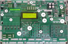
1) Redesigned playfield lamp matrix driver: Eliminates ghosting. Includes ‘Afterglow’ like functionality as standard. Configurable for lamp, LED, and mixed lamp/LED playfields.
2) Redesigned GI driver section: No heatsinks. Drives GI strings without flashing/strobing LEDs. ‘Afterglow GI’ like functionality as standard.
3) Easy to source/remove/replace fuses: Readily available 5 x 20mm fuses. Easy to replace without breaking the old fuse.
4) Power supply indicators and test points: Easy visual and multimeter checks of all board power supplies.
5) Handy fuse information: No need to check manuals to see which fuse to replace.
6) Powerful, switched-mode 5V supply: Replaces the troublesome 5V regulator to help eliminate machine reset problems.
7) New Bridge Rectifier design. Uses MOSFETs instead of diodes - no heatsinks required. Includes transformer protection circuitry.
8) MOSFET solenoid/flasher drivers. Monitors solenoid condition and warns users of faulty/aging solenoids.
9) LCD panel: Easy machine monitoring, testing and configuration.
10) User input switches: Easy configuration of board/machine features via the LCD menu system - no PC connection required.
11) Power supply connections for mods: Easy to connect to 12VDC and 9VAC for mods (e.g. replacement DMD modules).
12) Machine mod connectors: Allows monitoring of playfield switches and lamps to trigger 3rd party machine mods (optional).
13) Expansion port for custom boards. Direct connection to machine specific playfield LED boards (available separately).
The following text provides more detail on how the board works. Please let me know if you have any specific questions.
Lamp matrix LED turn on/off configuration: -
The standard WPC power driver board is designed to work with incandescent lamps. LEDs work differently and some people prefer to have the LEDs switching on and off more smoothly – requiring 3rd party hardware such as ‘Afterglow’.
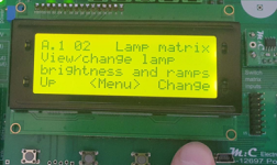
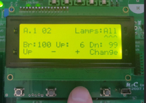
This new power driver board includes that functionality as standard. You can configure LED on/off rate settings – you can even change the brightness of the LEDs if required.
Settings can be changed for all LEDs in the matrix at the same time, or each LED can be changed individually. This permits fine tuning of each LED brightness and on/off rate to give smooth, ‘lamp like’ on/off transitions – without having to buy additional boards or make wiring changes.
Lamp matrix scan rate: -
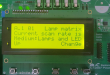
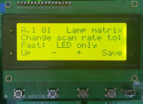
By default, the power driver board drives the lamp matrix at the incandescent lamp scan rate of 62.5Hz. The lamp matrix is intelligently driven to ensure lamps are fully turned off before lighting the next - eliminating LED ghosting without the need for specialised LEDs.
The lamp matrix scan rate can be changed to cater for mixed incandescent lamp/LED or all LED playfields. This speeds up the lamp matrix scan rate - eliminating lamp flickering.
Improved General Illumination driver section: -
No heatsinks are required as the GI strings are driven by MOSFETs using DC current – not TRIACs. The GI strings no longer suffer from the flickering which is most obvious when using LEDs.
The new GI driver section offers the ability to: -
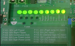
A single row of LEDs shows the state of all the power supplies. The LEDs are connected to the output of the supply. If the LED is on – the fuse is OK. The 50V supply is split into 5 separate outputs in the same way as the standard power driver board – this power driver board has a separate LED for each of these 5 outputs.
Just below the LEDs are the test points for GND, 5V, 12V, 18V, 20V and 50V. This makes it easy to use a test meter to test the quality of each of these power supplies during troubleshooting.
The new power driver board includes text that tells the user which fuse to change. The fuses are the more readily available 5 x 20mm type. The fuse holder type makes faulty fuses easy to remove without breaking the old one.
Bridge Rectifiers: -
The standard WPC power driver board uses diode-based Bridge Rectifiers to convert AC power from the transformer to DC power for the machine electronics. These Bridge Rectifiers are electrically inefficient and can get very hot – requiring heatsinks.
This WPC power driver board uses ‘ideal diode’ MOSFET Bridge Rectifiers. Powerful MOSFETs take the place of diodes and do not waste as much power as heat – meaning your machine runs cooler and more efficiently. Heatsinks are no longer required.
These Bridge Rectifiers also include current inrush limiting circuits to protect your transformer. When a machine is powered on, the instantaneous power drawn from the transformer to charge up the capacitors is huge. This puts a strain on the transformer which can shorten its lifespan. The built-in current limiting circuit reduces this inrush current significantly – which helps protect the transformer.
The new MOSFET Bridge Rectifiers are the same footprint as the old Bridge Rectifiers. They are available separately and may be fitted to existing power driver boards if required.
Improved solenoid/flasher section: -
The new power driver board uses MOSFETs instead of power transistors. By default, the board drives the solenoids and flashers in the same way as the standard WPC power driver board.
A common problem with solenoids is that they can start to break down and consume more power, generate more heat, and eventually fail. The new power driver board includes a ‘Learn’ feature which can be enabled via the LCD panel. This activates each solenoid in turn and assesses how much power each solenoid consumes.
The user can then enable the ‘Monitor’ feature. The power driver board will then monitor each coil during normal game play to see if its characteristics are changing – an early warning sign of a coil going faulty.
If a fault is detected, the user will be warned that something is wrong or (if the coil draws excessive current) the coil will be deactivated until repaired or overridden by the user. This helps prevent heat damage to playfields and coils.
Note that these features are in addition to the normal protection offered by the fuses.
By default, flashers are configured to work in the same way as the standard WPC power driver board. If required, individual flashers can be configured to give a lightning flash effect instead of just flashing once.
Additional power connections: -
Some aftermarket modules (e.g. PinLED DMD panels) require power to operate. Normally, the user must modify the wiring to fit these panels. The new WPC89 power driver board has additional connectors permitting easy connection to 9VAC, 12VDC and 5VDC.
‘Mod board’ connections: -
Some users add modifications to their machines. These often need to be triggered by playfield events (a playfield lamp, or a switch contact etc). The new power driver board allows the user to configure up to 3 outputs, where the state of each output is based on the state of lamp(s) or switch(es) – or both. These outputs are accessible at an onboard header.
M:C bus connector: -
Additional, game-specific boards will be available soon. These boards are drop-in replacements for the standard under-playfield lamp boards – E.g., Addams Family mansion area.
These boards are fitted with RGBW (Red, Green, Blue, White) LED’s. The colour, brightness and on/off rates of these LEDs can be changed by the user and connect to the new power driver board using a standard computer network cable (RJ45).
SMPS variant: -
The power driver board is designed to accept AC power from the standard transformer and cable harness. Replacement transformers are hard to find and expensive. The new power driver board can be ordered as an SMPS variant – meaning it is supplied with a single, 48V modern switched-mode power supply (SMPS) and cables to allow the user to replace a faulty transformer with a modern, single power supply.
That’s about it for now. I’m working hard on finishing up the firmware for this so it can be made available as a product. Please let me know what you think and if you have any questions or requests.
I’ve been working on a new WPC89 power driver board for some time now (there is a WPC95 version in the pipeline too). I thought I’d post some information about it to see if any of you would be interested in it.
The board is a drop-in replacement for the standard WPC89 power driver board – but it includes many new features that the user can enable and configure.
It can be installed without any wiring or machine modifications. By default, it is configured to work in the same way as a standard WPC89 power driver board.
New features at-a-glance:

1) Redesigned playfield lamp matrix driver: Eliminates ghosting. Includes ‘Afterglow’ like functionality as standard. Configurable for lamp, LED, and mixed lamp/LED playfields.
2) Redesigned GI driver section: No heatsinks. Drives GI strings without flashing/strobing LEDs. ‘Afterglow GI’ like functionality as standard.
3) Easy to source/remove/replace fuses: Readily available 5 x 20mm fuses. Easy to replace without breaking the old fuse.
4) Power supply indicators and test points: Easy visual and multimeter checks of all board power supplies.
5) Handy fuse information: No need to check manuals to see which fuse to replace.
6) Powerful, switched-mode 5V supply: Replaces the troublesome 5V regulator to help eliminate machine reset problems.
7) New Bridge Rectifier design. Uses MOSFETs instead of diodes - no heatsinks required. Includes transformer protection circuitry.
8) MOSFET solenoid/flasher drivers. Monitors solenoid condition and warns users of faulty/aging solenoids.
9) LCD panel: Easy machine monitoring, testing and configuration.
10) User input switches: Easy configuration of board/machine features via the LCD menu system - no PC connection required.
11) Power supply connections for mods: Easy to connect to 12VDC and 9VAC for mods (e.g. replacement DMD modules).
12) Machine mod connectors: Allows monitoring of playfield switches and lamps to trigger 3rd party machine mods (optional).
13) Expansion port for custom boards. Direct connection to machine specific playfield LED boards (available separately).
The following text provides more detail on how the board works. Please let me know if you have any specific questions.
Lamp matrix LED turn on/off configuration: -
The standard WPC power driver board is designed to work with incandescent lamps. LEDs work differently and some people prefer to have the LEDs switching on and off more smoothly – requiring 3rd party hardware such as ‘Afterglow’.
This new power driver board includes that functionality as standard. You can configure LED on/off rate settings – you can even change the brightness of the LEDs if required.
Settings can be changed for all LEDs in the matrix at the same time, or each LED can be changed individually. This permits fine tuning of each LED brightness and on/off rate to give smooth, ‘lamp like’ on/off transitions – without having to buy additional boards or make wiring changes.


Lamp matrix scan rate: -
By default, the power driver board drives the lamp matrix at the incandescent lamp scan rate of 62.5Hz. The lamp matrix is intelligently driven to ensure lamps are fully turned off before lighting the next - eliminating LED ghosting without the need for specialised LEDs.
The lamp matrix scan rate can be changed to cater for mixed incandescent lamp/LED or all LED playfields. This speeds up the lamp matrix scan rate - eliminating lamp flickering.


Improved General Illumination driver section: -
No heatsinks are required as the GI strings are driven by MOSFETs using DC current – not TRIACs. The GI strings no longer suffer from the flickering which is most obvious when using LEDs.
The new GI driver section offers the ability to: -
- Change the light output (brightness) for each GI string level.
- Change the way the GI brightness transitions from one level to the next.
- Configure GI strings to dim/turn off during game play to reduce backbox reflections on the playfield glass (like ‘Afterglow GI’).
A single row of LEDs shows the state of all the power supplies. The LEDs are connected to the output of the supply. If the LED is on – the fuse is OK. The 50V supply is split into 5 separate outputs in the same way as the standard power driver board – this power driver board has a separate LED for each of these 5 outputs.
Just below the LEDs are the test points for GND, 5V, 12V, 18V, 20V and 50V. This makes it easy to use a test meter to test the quality of each of these power supplies during troubleshooting.
The new power driver board includes text that tells the user which fuse to change. The fuses are the more readily available 5 x 20mm type. The fuse holder type makes faulty fuses easy to remove without breaking the old one.

Bridge Rectifiers: -
The standard WPC power driver board uses diode-based Bridge Rectifiers to convert AC power from the transformer to DC power for the machine electronics. These Bridge Rectifiers are electrically inefficient and can get very hot – requiring heatsinks.
This WPC power driver board uses ‘ideal diode’ MOSFET Bridge Rectifiers. Powerful MOSFETs take the place of diodes and do not waste as much power as heat – meaning your machine runs cooler and more efficiently. Heatsinks are no longer required.
These Bridge Rectifiers also include current inrush limiting circuits to protect your transformer. When a machine is powered on, the instantaneous power drawn from the transformer to charge up the capacitors is huge. This puts a strain on the transformer which can shorten its lifespan. The built-in current limiting circuit reduces this inrush current significantly – which helps protect the transformer.
The new MOSFET Bridge Rectifiers are the same footprint as the old Bridge Rectifiers. They are available separately and may be fitted to existing power driver boards if required.
Improved solenoid/flasher section: -
The new power driver board uses MOSFETs instead of power transistors. By default, the board drives the solenoids and flashers in the same way as the standard WPC power driver board.
A common problem with solenoids is that they can start to break down and consume more power, generate more heat, and eventually fail. The new power driver board includes a ‘Learn’ feature which can be enabled via the LCD panel. This activates each solenoid in turn and assesses how much power each solenoid consumes.
The user can then enable the ‘Monitor’ feature. The power driver board will then monitor each coil during normal game play to see if its characteristics are changing – an early warning sign of a coil going faulty.
If a fault is detected, the user will be warned that something is wrong or (if the coil draws excessive current) the coil will be deactivated until repaired or overridden by the user. This helps prevent heat damage to playfields and coils.
Note that these features are in addition to the normal protection offered by the fuses.
By default, flashers are configured to work in the same way as the standard WPC power driver board. If required, individual flashers can be configured to give a lightning flash effect instead of just flashing once.
Additional power connections: -
Some aftermarket modules (e.g. PinLED DMD panels) require power to operate. Normally, the user must modify the wiring to fit these panels. The new WPC89 power driver board has additional connectors permitting easy connection to 9VAC, 12VDC and 5VDC.
‘Mod board’ connections: -
Some users add modifications to their machines. These often need to be triggered by playfield events (a playfield lamp, or a switch contact etc). The new power driver board allows the user to configure up to 3 outputs, where the state of each output is based on the state of lamp(s) or switch(es) – or both. These outputs are accessible at an onboard header.
M:C bus connector: -
Additional, game-specific boards will be available soon. These boards are drop-in replacements for the standard under-playfield lamp boards – E.g., Addams Family mansion area.
These boards are fitted with RGBW (Red, Green, Blue, White) LED’s. The colour, brightness and on/off rates of these LEDs can be changed by the user and connect to the new power driver board using a standard computer network cable (RJ45).
SMPS variant: -
The power driver board is designed to accept AC power from the standard transformer and cable harness. Replacement transformers are hard to find and expensive. The new power driver board can be ordered as an SMPS variant – meaning it is supplied with a single, 48V modern switched-mode power supply (SMPS) and cables to allow the user to replace a faulty transformer with a modern, single power supply.
That’s about it for now. I’m working hard on finishing up the firmware for this so it can be made available as a product. Please let me know what you think and if you have any questions or requests.
