What's new
Pinball info

Register a free account today to become a member! Once signed in, you'll be able to participate on this site by adding your own topics and posts, as well as connect with other members through your own private inbox!

more Sega driver questions

cooldan

i like pizza
10 Years
Joined
Jul 21, 2011
Messages
7,102
Location
Ealing, London
so i'm still working with Space Jam and have made my list of what needs fixed, and am stuck - one coil and 4 flashers are out, so i'm wondering if there's a common link:

the problem i noticed initially was was a coil wouldn't fire in game or in test mode - coil #4 'jump ball top kicker', a 50V coil. the coil wrapper looked toasty with a stuck sleeve and the driver trans/mosf/whatever also looked a bit manky, so i replaced both coil/sleeve and driver at Q4. it still doesn't fire. i said i was also having trouble with some flashers - i replaced the bulbs but these ones all appear to be missing a drive signal or earth return - i was planning on replacing the TIP102s at Q21, Q22, Q23, Q26 and Q32 but maybe you fellas can point me in a better direction instead.

pic to break up text here - it serves no other purpose
gif hidinghomer.gif

for good measure i also replaced 4 IDC connectors with molex crimp-pin connectors, and this is when i realised that my game appears to be missing a wire from J10 pin 10, empty on my game but in the (crappy scan) manual on page 101 it says that there should be a yellow/black 24V AC output wire attached there. and it's not like yellow/black is a unique colour either, as i see three of these coming up in the looms - on the left, a yellow/black going to J13 pin 6 (for the lamp matrix), and on the right a yellow/black going to J11 (transformer AC input), and a yellow/black to CN4 on the CPU board (for something or other). so wtf is going on, is my game missing a wire to J10pin10 or not? Manual errors do happen.

and is there a common element that could be responsible for my troubled drivers at Q4, Q21, Q22, Q23, Q26 and Q32?

link to manual with ropey scanning: http://mirror2.ipdb.org/files/3879/Sega_1996_Space_Jam_Manual_Includes_Schematics.pdf

thanks fellas

@aaronhicksuk @lukewells @Jay Walker @Moonraker @pinballmania
 
Last edited:
I've had a little look and can't see a common element between the drivers you are having trouble with. Q4 is controlled by a HCT273 at U1. Q21, Q22 and Q23 are controlled by U3. Q26 and Q32 are controlled by U4. Have you tried reseating the ribbon cable between the CPU/Sound and Power driver boards? At first glance the only common link between these drivers appears to be the data lines to the CPU board.

Do you have the correct voltages at the coil (50v+) and flash lamps (20v)? Assuming you have a good power supply at the coil/flash lamps, do they work if you ground their control lines at the BOARD end? (Thereby eliminating the possiblity of any faults in the playfield wiring.)

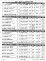
Use this table to look at what pins to ground, wire colours etc:

SJCoilTable.png
 
Hi Aaron thanks. Well I don't know what the coils and flashers are supposed to have at resting state, but all the coils including the 'dead' one have only 12-13V and all the flashers have only 3-3.5V. Which is fine if this is what they're supposed to have, can anyone confirm?

'Dead' 3 skill shot flashers grounded by Q21 all have 3.2V at the bulbs; The 4 under metal ramp serviced by Q22 all have 3.5V; the 4 at top L/R grounded by Q23 all have 3.4V; the 3 popper flashers grounded by Q32 all have 3.6V.

It's just the voltage for F2 the second arrow, for the captive ball, I can't test directly (Q26) but this is on a little board that also has flashers for arrow 1 and 3 on it, and they work just fine. I put a new flasher bulb in all of them. The orange wire going to the little bulb board has 3.5V.

So next is to try grounding them at the board end? What do I ground and where?

Can that rule out a playfield wiring issue?
 
Those voltages are all significantly lower than they should be. I'd expect to see at least 50v at the coil lug and around 20v at the flash lamps.

All of your problem flash lamps are supposed to be powered by an orange wire that originates from J6-P10. Do you have a solid 20v here? This pin/wire supplies all of the flashers in the game, so assuming that some are working then you should have a solid 20v at the board. This means there there is probably a break or a high resistance joint somewhere on the playfield. Try to find the orange wire in the loom from the backbox and follow it to the first flash lamp. What voltage do you have here? Again you should expect to see 20v or very close to it. Keep tracing the orange wire from flasher to flasher until you no longer have a solid 20v supply. When the voltage turns low then the fault must be behind it.

Are you sure all of the coils only have 12-13v at the lug or is it just the dead one? This voltage doesn't seem high enough to fire any solenoid with conviction! Power for the "Jump Ball Top Kicker" coil controlled by Q4 is supplied from J10/P4-5 and a Yellow/Violet wire. You should see at least 50v at the board and at every coil lug in the chain. Like the flash lamps you are looking for a break in the chain, a high resistance joint or broken wire etc.
 
You can try grounding the devices at board end but if they don't have a decent power supply then they won't work. If you want to try get a length of wire, fix one end to ground and then BRIEFLY touch the other end to the return pin of the device you want to test. The table above says what pin does what. e.g. The "Jump Ball Top Kicker" controlled by Q4 returns to J8-P5.

Don't waste your time with this until you have a solid power supply at the coils/flashers first.

Also I forgot to mention that touching meter probes on to soldered joints doesn't always provide good electrical continuity. If you aren't seeing the voltage you expect to then try to probe the metal lug itself rather than the ball of solder and/or press harder before writing it down as wrong. If you have a large resistance between your probe and what you are testing then your meter will read a lower voltage.
 
This is just what I need thanks buddy. J6 pin 10 is an orange wire with 22V. I followed it down the loom and at the very first flasher it gets to, there is 3.52V

Presumably I need to check the integrity of this orange wire all the way between these two points.
 
Although its possible, theres unlikely to be a break in the wire along its length. If there is a break in a wire its most likely to be in an area where it could of become trapped in something, like between the head and the cabinet or a playfield hinge etc. Dodgy joints and connectors are far more common problems so focus your attention on them first. In this case I'd look at the IDC connection at J6 P10 as its the most likely point of failure between the board and the first flasher.

What is the first flasher and does it work properly? I can't see how it can if it only has a 3.5v supply.
 
i already replaced J6 with molex crimp pins. no, the first flasher is one of the non-working ones, it's at top right and is #23 in the table you posted above, earthed by Q23

but one of the last ones in the chain, the 'final jam' flasher #17 (Q17) i just this second measured at 3.71V and that works just peachy
 
Hmm, this isn't being very logical at all! What happens if you manually ground the top right flasher with a piece of wire briefly? Make sure when you do so you are grounding through the lamp and not the supply directly! In other words ground the black/orange side of the lamp holder.
 
Do you still have 2 Space Jams? If you swap the power driver boards around you'll be able to see if the problems follow the board or stay with the playfield.
 
Hmm, this isn't being very logical at all! What happens if you manually ground the top right flasher with a piece of wire briefly? Make sure when you do so you are grounding through the lamp and not the supply directly! In other words ground the black/orange side of the lamp holder.
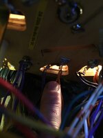
This is the first flasher - orange is the live wire (attaches and then heads off to the next one) and the other lug has the ground, doing likewise. Where do I ground it?images.tapatalk_cdn.com_15_12_22_eb13ee3bea3db6e99dc219c08403b701.jpg

Oh and yes I still have the first SJ but it's not easy to get to so if I can avoid going that route (go to garage, shift heavy bike, lower to ground, remove ratchet etc etc) then I'd like to try.
 
Nothing happened when I grounded that lug on the left. No flash.

Here's a video - not of no flash happening, of the generalised issue

 
Last edited:
You've already changed the lamp haven't you? Maybe the lamp holder is knackered, does it look clean and in good condition? With the machine switched off, whats the resistance between the 2 tabs on the lamp holder?
 
I'm glad (well not glad but u know what I mean) I'm not the only one with pinball frustration at the mo. Does that orange wire go through that connector that your hand was near at the end of the vid? If so could be dodgy pins
 
new bulb yes. 1.9 ohms between the tabs, is that ok?
Well its good that its not open circuit, theres not a lot of resistance in the lamp holder thats for sure! If you have a solid ground and a solid power supply and the lamps good then it should light up, otherwise something must be missing.

What meter are you using to take these measurements with dude cause a lot of this just doesn't seem plausible to me?
 
Ok, I've had a bit of a late brainwave. Its a lot harder for me to think of what to do when I'm not standing in front of the machine! How to narrow down the problem?

Disconnect the J6 and J7 connectors from the board. On the plug (playfield) side, measure the resistance between the supply (J6-P10) and each of the flasher returns: J6-P1 through 8, J7-P2, P4, and P7 through 9 (Info taken from the coil table). I'd expect to see a similar resistance between the supply and each return driving a single lamp, and proportionately lower resistances to each return driving more than one.

With careful probing you can also test whether the board is doing what it is supposed to, however be warned that its easy to damage if you short the wrong things together. Clippy probes or crocadile leads make things easier if you have them.

Again with the connectors above unplugged and the machine in flasher test mode, measure the voltage between the supply pin at J6-P10 and each of the return pins above. You should see a spikes of 20v each time the flasher should fire. If its not happening then something is isn't right here.

Your meter may not be fast enough to "see the flashes," so if you have problems you can always test with a lamp in a holder with 2 wires soldered on the end of it. In fact it would probably be safer for you to do so anyway! You could crimp a molex on 1 of the wires and trim down a connector to be 1 or 2 long. Plug that end in to the 20v supply and then just touch the other end on each of the return pins. If the board is working properly obviously you should expect to see the lamp flash on each return pin. The transistors are probably lame on any that don't work, or dry joints on the header pins or even somewhere else on the board.

You can check TIP122s easily in the board with your meter in diode test mode too. The old expect to see a 0.4v to 0.6v drop between the middle and each outer leg trick.

Don't give up, the meter is king and the answer is always obvious when you find it! :)
 
Last edited:
nice one Aaron, so you gave me three tests to do on all of these 13 connections -

test 1) resistance in playfield wiring from power to earth (tricky, as number kept changing)
test 2) check if board can make a bulb flash with playfield connected
test 3) DMM test of the transistors


coil 17 flasher 'final jam' ................. working ...........2.5 ohm .... flash ok ..... Q17 pass
coil 19 flasher 'jump ball' (2 bulbs)...working .............5.4 ohm .... flash ok ....... Q19 pass
coil 21 flasher 'skillshot' (3 bulbs) .....not working........1.2 ohm .... no flash ......... Q21 pass
coil 22 flasher 'basket ramp' (4 bulbs) ....not working....1.5 ohm .... no flash ............ Q22 fail
coil 23 flasher top L, top R' (4 bulbs) .....not working....1.5 ohm .... no flash ............... Q23 fail

F1 flasher 'L orbit arrow' ... ................ working...........1.8 ohm ..... flash ok ................. Q25 pass
F2 flasher 'captive ball arrow' ............not working ......2.2 ohm ....no flash ....................Q26 pass
F3 flasher 'basket ramp arrow' .......... working ...........1.8 ohm ......flash ok .................Q27 pass
F4 flasher 'jump ball arrow' .................working .........1.8 ohm .......flash ok ...................Q28 pass
F5 flasher R ramp arrow ...................working ..........1.8 ohm .........flash ok ...................Q29 pass

F6 flasher 'R orbit arrow' .....................working ........2.1 ohm ........flash ok ........................Q30 pass
F7 flasher 'drop targets' (2 bulbs) ..........working .........1.2 ohm ......flash ok .........................Q31 pass
F8 flasher 'pop bumpers' (3 bulbs) ........not working ......0.9 ohm .....tiny crappy half-flash ........Q32 pass

so in summary - i think i need to replace 2 transistors, but apart from that i'm stumped.
 
Last edited:
replaced Q22 and Q23 ...reflowed all header pins for J6 and J7 ... removed a ****load of cable ties to trace the orange power wire from its cradle to its grave and work out the order of power supply which is 23>19>32>23>22>(25, 26, 27)>17>21>(28, 29)>30>31 .... so i don't think i have a power issue, and as usual it's the earths

coil 21 flasher 'skillshot' (3 bulbs) .....not working........1.2 ohm .... no flash ......... Q21 pass
coil 22 flasher 'basket ramp' (4 bulbs) ....not working....1.5 ohm .... no flash ............ Q22 pass
coil 23 flasher top L, top R' (4 bulbs) ..... working....1.5 ohm .... flash ............... Q23 pass
F2 flasher 'captive ball arrow' ............not working ......2.2 ohm ....no flash ....................Q26 pass
F8 flasher 'pop bumpers' (3 bulbs) ........not working ......0.9 ohm .....tiny crappy half-flash ........Q32 pass

now i have one less non-working flasher (down to 4) and still the non-functioning coil #4 (replaced Q4, repinned J8, not repinned J10 yet)

/sigh

images.tapatalk_cdn.com_15_12_23_2c4b628621906ad5889fc2b064a107a1.jpg

Oh and here's that lamp test in video
 
Last edited:
Can you do it like Netflix please Dan and air all episodes in one go? :) some good fault finding lessons here, I'm sure the fix is pretty close now.
 
Looks like all your problems lie on the power driver board now then mate. What drivers still aren't working properly?
 
You can test to see if the transistors switch a load correctly by following this procedure detailed in the manual:

upload_2015-12-24_13-29-55.png

If the flashers/coil work using the above procedure then there is an issue with the logic circuitry behind the transistor. If they don't then the problem lies with the transistor itself or its continuity to ground or the header pin. (Providing everything on the playfield is good!)

Have you tried checking continuity and resistances between points on the board itself? There isn't much to any of these driver circuits so they should be pretty straightforward to troubleshoot. Taking the problem driver you have at Q32 as an example:

The signal to switch on comes from the HCT273 chips at U4, pin 19. It goes through the diode at D215 and 620 Ohm resistor at R2, then on to the base of the TIP122 at Q32. The only other component is a 22k "pull down" resistor, R215. Like the name suggests its purpose is to ensure that the voltage of this line is pulled down to ground (logic level 0) when there is no signal from the HCT273 to switch the transistor on.

Are all of these components still in spec and are all the traces/joints solid? Test for continuity/resistance between the components. It can be useful to test a component from the legs of the components either side of it to prove that its soldered joints are good, but you have to be careful with parallel paths as they will cause strange/useless readings. For example you could test diode D215 by probing leg 19 of chip U4 and the leg of resistor R32 it is connected to.

A better explanation of pull up/down resistors here: https://en.wikipedia.org/wiki/Pull-up_resistor

You really need a scope or a logic probe to test if the chips are working correctly, but doing so isn't really any more difficult then anything else you have done so far. Keep at it, YOU will find the problem eventually. Although it doesn't always seem so everything always happens for a reason, there will be a logical explanation for the faults.
 
Back
Top Bottom