What's new
Pinball info

Register a free account today to become a member! Once signed in, you'll be able to participate on this site by adding your own topics and posts, as well as connect with other members through your own private inbox!

lamp matrix issue on whitewater

AlanJ

Site Supporter
Joined
Dec 27, 2017
Messages
7,760
Location
Leeds, West Yorkshire
Alias
Alan
hello folks

got a lamp matrix issue on whitewater. whenever a lamp in any column and row is on it also lights the corresponding lamp in column 4. eg if column 2 row 4 is on then. col 4 row 4 is on. and if col 1 row 5 is on then col 4 row 5 will also be on.

the col 4 lamps are not on all the time either.

this machine has led ocd fitted so that complicates matters a bit.

i guess it’s probably the tip107 transistor that controls column 4 it looks like it’s always “on”. or suppose could be the ic further down the line

i suppose it’s time to dig out the logic probe and take a look [emoji102]

any suggestions on what to try most gratefully received


Sent from my iPhone using Tapatalk
 
I tested the outputs from the main board for the columns, and it all appears ok, I disconnected the OCD board and connected the lamp matrix rows and columns connecters back to the IO board directly and the problem has gone away (but the LED's look bloody awful without the OCB board)

I tested the OCD board with power connected but nothing on it's inputs or outputs. All the outputs for the columsn were high. I then connected the input of the OCD to the IO board for rows and columns. All the colums are strobing from high to low, EXCEPT column 4 which is permanently HIGH, so it appears that the problem is the OCD board itself, given that there was nothing connected to the outputs of the LEDOCD board at this stage.

I installed the LED OCD software on my laptop and hooked it into the board, I was hoping there would be some setting tha was a t fault, but no such luck. I used the test facility in there and it just confirmed the same problem as the lamp test I did yesterday.

So, deffo looking like the LEDOCD board itself, I dont have a spare, so will have to live with it until I can repair or replace it.

I've knackered (and since repaired) a couple of the OCD boards just by either shorting some lamp holders while doing other fixes or shorting the board to the backbox plate.

Both times it was a transistor on the OCD board that needed replacing.

I only have the slightly older rev4 boards with through-hole components, not the mini type, at least for my WPC games.. Details.

And i totally agree - the LEDs do look proper ****e when you take the OCD board out.
 
Last edited:
Closer look at the LEDOCD Mini board and there are a number of small transistors on the bottom side, SMD of course. @Spadge kindly had info that identified the transistor part numbers for the rows and columns Mosfets. They are cheap to buy, just going to be a bit fiddly to replace. Will update on progress.

As it's only three pins on a transistor, I'm not sure I'll need a hot air rework station. I have seen whole multi pin chips being removed with just a std soldering iron and some "SMD removal alloy" - looks quite cool how that works, it's basically a very low melting point metal, once heated up it stays hot for a long time, and in turn keeps the exiting solder molten for longer, allowing time to heat up all pins of a chip.

Will advise on how I get on.........
 
so had a go a desoldering and replacing an smd component Q4

it’s hard on the eyes but fairly easy. helped having a bottle of flux.

Pleased to say whitewater now working perfectly

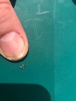
here’s the new transistor: tiny!!! i got 6 for £3.20.

d62233be62198cc55bd2412dcd5c498f.jpg


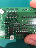
and the repaired board:
5777bbd677216746eff211c90522a3f9.jpg

as a point to note. the rev 3 ocd boards (the latest version of the mini boards) use much bigger and more robust transistors.


Sent from my iPhone using Tapatalk
 
Holy crap.. how on Earth do you even begin to remove and replace one of those!
It took a white, never done any smd stuff before, but as it only had 3 legs, it was easy to heat up the single pin side and flip it up, then then other 2 were easy. Soldering the new one on was harder, but essentially the same, solder on the single pin side first. I used a pair of magnifying goggles so I could see it. Std soldering iron, with a pointed tip. Smd devices are well soldered on, so flux and new solder is needed to get the old solder to melt.

I wouldn't fancy doing a multi pinned smd chip to be honest.
 
Back
Top Bottom