What's new
Pinball info

Register a free account today to become a member! Once signed in, you'll be able to participate on this site by adding your own topics and posts, as well as connect with other members through your own private inbox!

IJ Pop Bumper Pics Needed!

Steve

Registered
10 Years
Joined
Jul 21, 2011
Messages
774
Location
Maldon,Essex
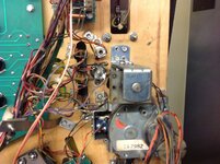
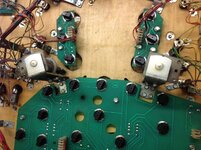
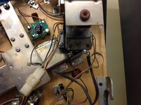
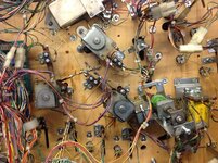
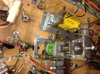
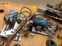
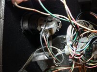
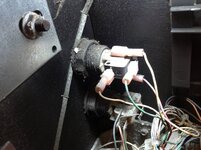
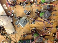
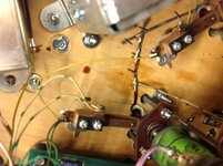
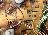
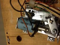
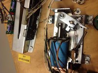
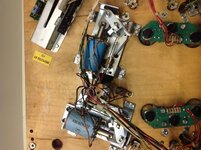
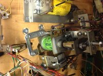
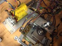
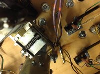
Does anyone have pictures of the pop bumpers on the underside of a Williams IJ?

I can't find any reference as to how the bumper light legs are soldered underneath the playfield and like an idiot didn't take any pictures of this area.

Any help appreciated!
 
Thanks Geoff, those pictures were perfect! In fact almost all the staples I used went back in the same factory holes!

IMG_2085.jpg
 
use ring terminals on the end of the stranded wire, then a small screw to hold it down and make contact with the lamp holder lead , no fiddly soldering to be done then, so much less chance of solder splashes. :)
stan
 
That is one of those tips that I just don't understand why they were not made that way. That has to be easier than what they gave us, I guess the cost of the ring terminals and screws would have added up over a run.
 
use ring terminals on the end of the stranded wire, then a small screw to hold it down and make contact with the lamp holder lead , no fiddly soldering to be done then, so much less chance of solder splashes. :)
stan

Sounds a great idea Stan, I'm hopeless at soldering so this makes more sense anyway.
 
Do these help? ;-)
 

Attachments

  • ImageUploadedByTapatalk HD1375434657.587615.jpg
    ImageUploadedByTapatalk HD1375434657.587615.jpg
    130.2 KB · Views: 8
  • ImageUploadedByTapatalk HD1375434704.196392.jpg
    ImageUploadedByTapatalk HD1375434704.196392.jpg
    124.4 KB · Views: 10
  • ImageUploadedByTapatalk HD1375434816.155187.jpg
    ImageUploadedByTapatalk HD1375434816.155187.jpg
    148.9 KB · Views: 6
  • ImageUploadedByTapatalk HD1375434941.398135.jpg
    ImageUploadedByTapatalk HD1375434941.398135.jpg
    142.9 KB · Views: 7
  • ImageUploadedByTapatalk HD1375434975.763214.jpg
    ImageUploadedByTapatalk HD1375434975.763214.jpg
    123.3 KB · Views: 5
  • ImageUploadedByTapatalk HD1375435023.333690.jpg
    ImageUploadedByTapatalk HD1375435023.333690.jpg
    105.7 KB · Views: 5
Progress has ground to a halt again!

I'm now connecting all the wiring back up and have come up with a problem. The wires from the optos on the right (plastic) ramp are raw i.e. they are bare with no plug (see pic attached).
I must have taken pics at the time, but they've disappeared along with the others. It's been so long since I removed them I can't remember where they went?
Problem is there is some non-factory connectors in the vicinity and I'm guessing some sort of botch-job in the past? (See other pics).
any ideas?


IMG_2112.jpg IMG_2116.jpg IMG_2117.jpg
 
Steve, I hope these help. On the coils, most have the right lug as the thin wire, but for the idol release, mode kick out, underneath ramp proper, drop targets and the totem drop target have it the other way round.
Back box image shows the cable twist plus the violet wire connection.
 

Attachments

  • ImageUploadedByTapatalk HD1376736508.413476.jpg
    ImageUploadedByTapatalk HD1376736508.413476.jpg
    136.8 KB · Views: 2
  • ImageUploadedByTapatalk HD1376736564.708213.jpg
    ImageUploadedByTapatalk HD1376736564.708213.jpg
    158 KB · Views: 2
  • ImageUploadedByTapatalk HD1376736652.656616.jpg
    ImageUploadedByTapatalk HD1376736652.656616.jpg
    141.7 KB · Views: 2
  • ImageUploadedByTapatalk HD1376736753.920940.jpg
    ImageUploadedByTapatalk HD1376736753.920940.jpg
    141.1 KB · Views: 1
  • ImageUploadedByTapatalk HD1376736794.947845.jpg
    ImageUploadedByTapatalk HD1376736794.947845.jpg
    146.6 KB · Views: 1
  • ImageUploadedByTapatalk HD1376736848.223196.jpg
    ImageUploadedByTapatalk HD1376736848.223196.jpg
    103.3 KB · Views: 1
  • ImageUploadedByTapatalk HD1376736902.331717.jpg
    ImageUploadedByTapatalk HD1376736902.331717.jpg
    191.8 KB · Views: 1
  • ImageUploadedByTapatalk HD1376736931.896522.jpg
    ImageUploadedByTapatalk HD1376736931.896522.jpg
    140.5 KB · Views: 2
  • ImageUploadedByTapatalk HD1376736960.731168.jpg
    ImageUploadedByTapatalk HD1376736960.731168.jpg
    145.4 KB · Views: 1
Sent from my iPad using Tapatalk HD
 

Attachments

  • ImageUploadedByTapatalk HD1376737572.520171.jpg
    ImageUploadedByTapatalk HD1376737572.520171.jpg
    132.5 KB · Views: 1
  • ImageUploadedByTapatalk HD1376737606.904362.jpg
    ImageUploadedByTapatalk HD1376737606.904362.jpg
    133.5 KB · Views: 1
Cheers Geoff, my button wiring matches yours so no problems there. That's one less thing to worry about!
 
Problem is there is some non-factory connectors in the vicinity and I'm guessing some sort of botch-job in the past? (See other pics).
any ideas?

Yep, match wires from the optos with the ones in the block eg. grey and yellow to grey and yellow, black to black, orange and red to orange and red, etc.
 
Yep, match wires from the optos with the ones in the block eg. grey and yellow to grey and yellow, black to black, orange and red to orange and red, etc.

Yep, that worked. All switches are now working perfectly. (Everything else doesn't)!!
 
We had most of the solenoids working yesterday apart from the one that blew the fuse.
Is this in test mode that none of the solenoids work? If so, check connections and fuses as we had most of them working yesterday.
 
I don't know what the effects of that extra amp would be and we know there is an issue causing it to blow so I would get more of those mini fuses first. It might be that 2.5 is too small as it is meant to be 3 but again I can't say for sure.
 
Go to one stop pinball and buy some of his circuit breakers. Stick it in there and whenever it pops you just have to press a button to reset it. That will help you find the problem without using all your fuses up. I think they're £2.50 each.
 
Go to one stop pinball and buy some of his circuit breakers. Stick it in there and whenever it pops you just have to press a button to reset it. That will help you find the problem without using all your fuses up. I think they're £2.50 each.

Sounds like a good idea, I've just ordered one!
 
I don't know what the effects of that extra amp would be and we know there is an issue causing it to blow so I would get more of those mini fuses first. It might be that 2.5 is too small as it is meant to be 3 but again I can't say for sure.

I took a chance with a 4 amp and it blew straight away on start-up.

Everything seems to be working fine apart from the left flipper and the idol ball release gate? It reports only one error on start-up,

"ER. SINGLE DRP. BAD CHK. SWITCH/COIL"

Weird thing is, the single drop target is working fine?

I turned it on last night after fiddling with it, and it played a complete game with no problems apart from the left flipper and idol ball release not working. All switches are working, ramps, gates, popper, mini playfield, idol, jet bumpers, slingshots, everything is doing what it's supposed to be doing. But stick a 105 fuse in and it blows either on start-up or during the game? I've swapped out the left flipper cabinet board (no change) and switched the wiring on the idol ball release coil in case I had it round the wrong way (no change).
 
Back
Top Bottom