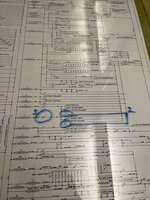
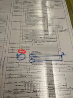
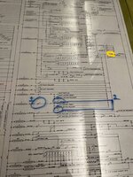
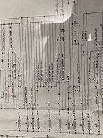
I see the circuit for relay 'I' as, L to R, supply/ a normally closed switch on relay 'J'/ four parallel normally open switches, "Left Roto", "Left Center Target", "Left Bottom Rollover" and a switch on Relay 'I'. Though the last of these has a different destination. The two endings of these circuits move off upwards on the drawing.
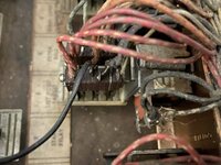
Re. the additional picture just added, '2' returns via a n/closed motor switch at the motor position '2B', the other branch via an n/c switch at motor '1C'.
That additional wire has been added to a normally open switch on relay 'I', the one shown on the companion relay 'J' is n/closed. Looking further up the diagram i see an N/O contact on relay 'I' shown at one side of the wiper for "Left Advance Unit". There's another near the wiper for "Roto Unit", left of that, across from relay 'H'. And another L/R pair with relay 'J' on the exits from wipers for the "Advance Units" themselves, next up from relay 'L'. There may be others on the lighting side, too.
As a rule with Gottlieb drawings, the further up the solenoid side a component is placed, the more likely it is to be shut off by the Game Over relay, e.g. the flippers are on the very top line, with the coin switches at the lowest on the transformer secondary, if not the primary
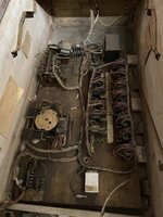
Another point with Gottlieb e/m's is the wire insulation. Most original wiring is fabric covered, anything with plastic insulation probably carries mains or 'line' voltage so should be regarded with suspicion.
 any help where I should be looking for the connections ?
 any help where I should be looking for the connections ?
