What's new
Pinball info

Register a free account today to become a member! Once signed in, you'll be able to participate on this site by adding your own topics and posts, as well as connect with other members through your own private inbox!

Help with wpc powerboard schematics

RudeDogg1

Site Supporter
10 Years
Joined
Dec 27, 2012
Messages
8,516
Location
Barnstaple, Devon
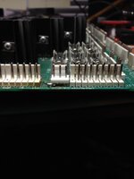
Upon putting bsd back together I noticed a rather horndously hideous botched repair that I had to rectify correctly
uploads.tapatalk_cdn.com_20170729_ccffa50a673a7608962a1f1869a315f3.jpg

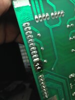
It's not even level with the rest of it! On closer inspection this is due to the tracks are lifted as are the through holes and the pads are gone, also the trough hole on pin 1 is lifted.
uploads.tapatalk_cdn.com_20170729_b51afe28eb8ef2e3674ba424f8307f98.jpg

Now I'm totally crap at reading schematics but the wpc one I found don't look right all the PIN numbers are jumbled and the key is in the wrong place (should be pin 9). All I need to know is where do the tracks for pin 1,11 & 12 on J115 go to please
 
Yes no 1 op bodge that the right thing to do is remove the full 12 pins and replace the lot I don't have a schematic to hand but if you hold the board up to the light then it's pretty easy to see off the top of my head those pins go to the fuses and the centre pin in each triac
 
ty pin 12 apears to be q12, 11 the fuse and 1 just goes to the edge of the board would that be the ground? if so do I take a jumper to the silver ground patch in the corner?
 
... schematics but the wpc one I found don't look right all the PIN numbers are jumbled and the key is in the wrong place (should be pin 9). All I need to know is where do the tracks for pin 1,11 & 12 on J115 go to please


Often on schematics the pins of connectors, ICs etc. are reordered physically (but remain correct numerically) to allow a cleaner drawing layout

Anyway, according to the schematic manual 16-9473-1

pin 1 : GND
pin 11 : Q14
pin 12 : Q12

good luck
 
Back
Top Bottom