What's new
Pinball info

Register a free account today to become a member! Once signed in, you'll be able to participate on this site by adding your own topics and posts, as well as connect with other members through your own private inbox!

Gottlieb system 3 (Freddy) switch matrix issue

cooldan

i like pizza
10 Years
Joined
Jul 21, 2011
Messages
7,100
Location
Ealing, London
my new Freddy has some switches out - A2, A3, A4, A5, A6 and A7. all in the same row of the matrix.

switch A1 is 'not used', but A0 (boiler room trough opto) works just fine. so i got on the phone and talked about it with Calimori and with GrizZ, and i sent them both photos and the manual, and tried out lots of stuff already but still no success.

horsey is rude.jpg

so what did i do so far? (i hear you ask)

well, i did everything i was told to do by those more intelligent than me:
@ i took one suspect board off (driver board A3) and tested all 44 transistors, and all 50+ resistors, and all 30+ diodes on it with my multimeter. all passed.
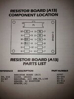
@ i took another suspect miniboard off (resistor board A13), and tested all the stuff on there. all passed.
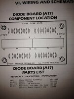
@ i took another suspect miniboard off (diode board A17), and tested all that lot. passes all round.
@ i physically traced the wires to and from each of my suspect switches - which involved removing over 80 cable ties from the various looms - and checked continuity, which all worked ok.
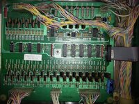
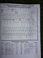
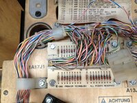
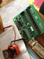
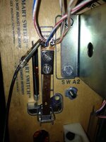
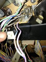
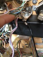
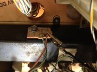
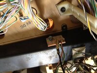
Freddy board A3.jpgIMG_4910.JPGIMG_4927.JPGIMG_4937.JPGIMG_4922.JPG IMG_4938.JPG
IMG_4933.JPGtesting.jpgIMG_4939.JPGIMG_4940.JPG


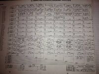
here is the switch matrix from the manual for you clever types
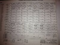
IMG_4936.JPG

phew, this is pretty heavy going. let's take a breather

gif bouncy2.gif

ah, that's better.

ploughing on.....
reading a bit about it, including all the links and stuff that GrizZ sent me, i know that one failing of sys 3 Gottliebs was that they used the same wires for the lamp matrix as the switch matrix, so i was reading that sometimes the key could be a bulb issue.

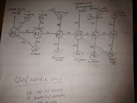
and here is the lamp matrix
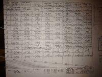
lamp matrix.jpg


when i test the lamps in the diagnostics, they all pass except for lamp 10 and lamp 11, the pop bumber lamps. i took the bulbs out, tested them (fine) and even tried new ones in case the bulbs were not ok. these lamps won't light. please can someone point me towards what i should try next?

thanks fellas


loads more animated booby gifs coming up. i will try to keep them clean (ie no nudity) but beyond that can make no promises. it is a large collection.
 
Sorry dude can't help but I do enjoy your posts for the boobs and humour!! I do however have a fully populated big hurt play field if you need any spares. Let me know if I can help mate!
 
If A0 is working then you have a break somewhere between A0 and A2.

Is A2 where the smart switch has been replaced? if so did they wire it incorrectly?

You could add a wire to go from A0 to A2 and see if that solves the problem, which would confirm a break.

Unlikely to be the cause coz A0 is working but I see A0 is on the opto board and would consider reflowing the back of the header pins in case there's a hairline crack (in particular 1A25J1 pin 2).

Lamps 10 and 11 are probably in need of a new bulb holder, suspect the old ones haven't survived the pop bumping over the years...
 
Cheers Peter, I've been hoping for some more good ideas and you've given me two.

Can you tell me again where to reflow? I'm not very good yet at deciphering the nomenclature of boards and sockets.

No booby pic as I'm out on tapatalk (yes I'm a sad addict, but I need to also check the footy scores hoping for a Spurs win)
 
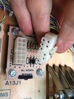
For example: In the 5th picture above you're showing a plug in your hand next to the socket. The PCB (A13J1) with the socket on you flip it over and re-solder the socket pins to remove any hairline cracks. Like I said above I don't think you will need to in this case with the opto board 1A25J1.
 
Right. I followed the wires from A0 (boiler trough opto) to the opto board and to two other opto switches but not directly to A2.
I also reflowed all pins on both connectors on the opto board but no change, A2 to A7 still not registering. Then i made a long jumper wire to make that connection you suggested, but unsure where to connect A2 and A0 as both have two terminals. At A0 end do I connect from the white or the black bit?


gif cameron shagging maggie.gif
 
The switch matrix image is no longer showing in the thread so I can't say which colour wire...!
 
well, i did my best: i made a jumper wire and tried joining the left hand contact of A2 to each of the four contacts of A0, then the right hand contact of A2 to those same four points. None of them made the switches register when pressed in switch test mode :(

in other words, i tried this
A2 left.jpg A0 top left.jpg
and this
A2 left.jpgA0 top right.jpg
and this
A2 left.jpgA0 bottom left.jpg
and this
A2 left.jpgA0 bottom right.jpg


then i moved to the other side of A2, and tried this
A2 right.jpgA0 top left.jpg

and this
A2 right.jpgA0 top right.jpg

and this
A2 right.jpgA0 bottom left.jpg

finally this
A2 right.jpgA0 bottom right.jpg


for the sake of completeness, here is where all the wires from switches go:

i traced the wires from A2 and they go like this:

311 to board A13J1 pin 7
311 to switch A3 (this 311 wire goes all along the chain, A2 to A3 to A5 to A7 to A6 to A4. i don't know why they're out of sequence, is that relevant?)

622 to switch 23 (outhole) which works fine, and which is also connected to A3
622 to switch 92 (left inlane) which works fine


from A3, 311 continues to A5
also 336 goes to 93 (right inlane) and also to 23 (outhole)

from A5, 311 continues to A7
also 655 goes to 15 (top right kicker) which has a diode or something on it, and also to 95 (top centre target)

from A7, 311 continues to A6
also 677 goes to 97 (soul target 3) and also to backbox board A1 connector J5 pin 7

from A6, 311 continues to A4
also 666 goes to 96 (soul target 1) and also to 16 (inner bullseye target)

at A4, 311 ends
also 644 goes to 14 (bottom left popper) and to 34 (bottom motor stop)

freddy switch matrix.JPG
 
Fixed!

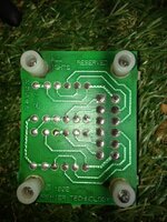
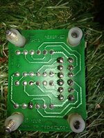
thanks to Peter Blakemore (yodamoonraker) we diagnosed it by measuring voltages on little board A13J1, and tracked it to a cracked solder joint. i don't know how he worked it out, but he told me to check voltages at pins 1, 2, 3, 4, 7, 8, 9 and 12, and what should be the same as what. it wasn't, so i had a closer look - check out the bottom left one of the two vertical columns, it has a little inner circle ring on it.

before:
1.jpg

i reflowed this (and all the other pins) and now the voltages were all the same, and the switches all worked!

after:
2.jpg


____________________________________________________________

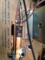
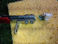
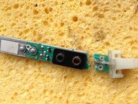
actually, i tell a lie when i said that everything was now hunky dory - switches A2, A3, A6 and A7 were working, but A4 and A5 were not, and i traced this to the fact i had accidentally snapped the smart switch at A5 with all the lifting and lowering of the playfield. not sure about A4 yet but i'll worry about that later, it may just be a downstream fault related to snapped A5 i'm guessing.

not such a smart switch now!
3.jpg6.jpg

any point in trying to fix this by resoldering the three traces? or just replace with a leaf switch? if the latter, are these cheap and easy to come by?

ignoring this new issue with the snapped switch, it felt awesome to fix this switch matrix issue by reflowing a pin, this was new for me.

thanks again Peter!
 
Well done Peter for giving Dan the direction on this, trouble shooting is one thing, to pass instructions to another person for them to perform the trouble shooting is far harder.
 
Yes you can get them but they ain't cheap,my main man gaz shiels has helped me out with a couple top bloke!
 
Back
Top Bottom