OK Peter
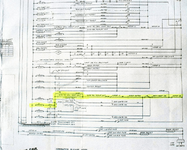
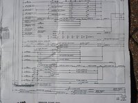
Here is the circuit we are looking at

You didn't give me the table to interpret the letter codes, but I'm using a schematic from a Fun Land and it looks similar to yours in this area
Before I get into any detail, I should say that it is generally accepted that Gottlieb schematics are drawn in the following way (copied from the Pinrepair website which is the "
bible" for fixing games

):
"How are the Schematics Drawn?
There's a fair amount of confusion about this. My understanding is that schematics are drawn with the game reset (all score reels at zero), ready to play, for one player at first ball, and the game's power is turned off. If you're confused about whether the schematics are drawn with the power on or off, just look at the Hold relay's switches - this relay is energized when the game is on, so if the schematic were drawn with the game "on", then these Hold relay switches would be triggered. Note on Gottlieb games the schematics are also drawn with zero credits on the credit wheel (Williams and Bally schematics seem to be drawn with credits on the wheel.) "
So - your start relay solenoid is shown on the left of the highlighted path
Then, working from the main power circuit (red white wire) on the right hand side there are three normally closed switches before you get to the replay button (Motor 2B, An anti cheat switch (maybe behind the door or on the mechanism board) and on the SB relay.
You should therefore have continuity all the way from the 15A fuse to one side of the replay button switch - if not check out those three switches.
If that checks out OK then working onwards from the replay button you have another motor switch before the replay unit
The switch on the replay unit is the one I think gets bypassed by your freeplay modification, but in any case you said you had tried adding credits manually on the wheel. Obviously normally if there are no credits on the wheel this switch is open and you can't start games from the button
After the replay unit you have two paths and this is where it might get a bit confusing (for you and for me!): This is the way I interpret it:
The "normal" route to starting a game will be through the zero position switch on the ball count unit - this will be closed in any state of the machine except when you have just started a game when it will be open to prevent you accidentally starting two games and thereby using up 2 credits by holding in the replay button too long
Obviously this would mean if the game was tilted or turned off as soon as you had started a game it would subsequently be impossible to start a game as the ball count unit would be at zero and the switch would be open interrupting the circuit
Hence the need for the alternate route - when the game is in "Tilt" the switch on the Tilt relay (TB on your game I think, T on Fun Land) will be closed, completing the circuit from the replay button to the start relay
It's possible I've got this wrong, but it is clear that the two switches are ones to check in solving this problem in any case
The final bit of the circuitry is to do with multiple coin chutes so you may not have a W relay, but if you do there is a switch on there which needs to be closed.
Again, I think you should be able to check the integrity of the second half of this circuit by testing continuity between one side of the replay button switch and the start relay coil.
When checking out the various switches remember that the schematic shows you the colour of the wires you are looking for, so that should make it easier to identify the relevant switches
Hope that helps - let me know how you get on


