Hi everyone,
I've been working on my first Pinball machine, and I'm finally up to my last issue before I make a big parts order from America,
The left Pop bumper doesn't seem to be firing, I went into the relay test mode, and manually firing it works fine, so I went into the switch matrix test mode, and it looks like the switch isn't beign regsitered.
I used a multimeter to check continuity and the switch seems to work (compared to the right pop bumper)
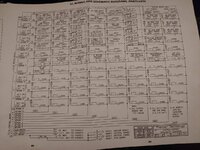
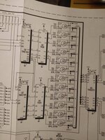
I have the repair manual and have watched several videos on how switch matrixes work, I understand the basics but I'm a little lost reading the schematic.
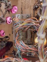
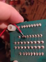
The switch has continuity up to the board I've pictured, which is the Diode board for the switch matrix
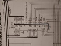
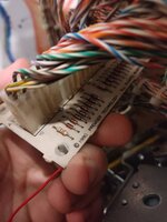
I've tried bridging pins 11 and 12 of the matrix, so that when the right pop bumper is fired, the left one should trigger too ,but that doesn't seem to do anything.
Honestly I think I'm slightly out of my depth, most of the issues I've googled have been around entire strobe lines being out, or when one switch fires another does. I assume just one switch not working means it should be something isolated and simple to fix.
Could anyone give me any advice as to how to isolate the problem?
Thanks so much.
I've been working on my first Pinball machine, and I'm finally up to my last issue before I make a big parts order from America,
The left Pop bumper doesn't seem to be firing, I went into the relay test mode, and manually firing it works fine, so I went into the switch matrix test mode, and it looks like the switch isn't beign regsitered.
I used a multimeter to check continuity and the switch seems to work (compared to the right pop bumper)
I have the repair manual and have watched several videos on how switch matrixes work, I understand the basics but I'm a little lost reading the schematic.
The switch has continuity up to the board I've pictured, which is the Diode board for the switch matrix
I've tried bridging pins 11 and 12 of the matrix, so that when the right pop bumper is fired, the left one should trigger too ,but that doesn't seem to do anything.
Honestly I think I'm slightly out of my depth, most of the issues I've googled have been around entire strobe lines being out, or when one switch fires another does. I assume just one switch not working means it should be something isolated and simple to fix.
Could anyone give me any advice as to how to isolate the problem?
Thanks so much.
Attachments
-
 IMG_20211012_184633.jpg103.2 KB · Views: 9
 -
 IMG_20211012_184650.jpg51.3 KB · Views: 24
 -
 IMG_20211012_184708.jpg179.1 KB · Views: 21
 -
 IMG_20211012_184742.jpg95.9 KB · Views: 25
 -
 IMG_20211012_184755.jpg109 KB · Views: 10
 -
 IMG_20211013_182924.jpg59.6 KB · Views: 9
 -
 IMG_20211013_182929.jpg70.7 KB · Views: 10
