What's new
Pinball info

Register a free account today to become a member! Once signed in, you'll be able to participate on this site by adding your own topics and posts, as well as connect with other members through your own private inbox!

Flintstones Issue with trough solenoid and column 1 Lamps

Renvil

Registered
Joined
Dec 29, 2019
Messages
76
Location
Mansfield, uk
Hey folks

Hope you're all keeping safe!

I have an issue that i've reached the limit of my diagnosis skills. Stangely, BOTH these issues started at exactly the same time.

Issue 1 : Ball Trough Solenoid

The ball trough solenoid no longer functions. All other solenoids on that circuit work. If i test from the plug J130-1 to the solenoid all is well ~ 0 ohm. I am getting no voltage to the solenoid when in a repeat test. Is there any way to test that the pin on J130-1 is sending the ~50v required?

Issus 2: Lamp Circuit Column 1 is not lighting ANY bulbs on the column. BUT if i power off the machine for a while and power it back on, the Column works for 5 seconds or so before they start to flicker and then stop. If i do a quick reboot, they continue to not work.

Please feel free to ask additional questions to help me narrow down the issue.

Thanks in advance (and hope)
 
Hi Renvil,

You should be seeing 50V on that coil at all times. The power driver board will switch one side of the coil to ground to compete the circuit, energising it.

If you're not seeing 50V on it, try measuring another coil just to satisfy yourself that you get a valid reading and then check wiring between coils (they're looped together in groups).

Let us know what you find!

Tim
 
Issue 1. Test either side of the coil when in attract ( ie not being pulsed ) to ground in the cab. Should read 73v or so.

issue 2. You need a logic probe ideally to trace the strobe signal through the drive circuit for col1 to see where the issue is

can send the board to me to check and repair it if required
 
Thanks all

I do get 73v on both sides of the coil
In attract mode.


Sent from my iPhone using Tapatalk
 
Sound like you might have some bad transistors. With the board out of the machine, try measuring resistance between all 3 legs - if any read 0 ohm change it.

Lamp column 1 is Q96. Ball trough is Q82.
 
Sound like you might have some bad transistors. With the board out of the machine, try measuring resistance between all 3 legs - if any read 0 ohm change it.

Lamp column 1 is Q96. Ball trough is Q82.
If a transistor is shorted then the coil would be locked on not off. Most likely a wiring issue or the coil with a broken wire
 
How do i know which side is the drive side? (Sorry for my dumb newbie questions)
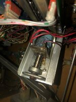
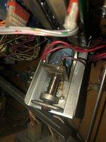
Share a pic and we can tell you. If the coil has a diode it will be the wire on the non banded side and wire itself will be a thinner one with a striped colouring usually
 
Before doing any of this does the right slingshot work?

If not then you have a data problem between the cpu and driver board. Reseat the short grey ribbon cable and if that doesn’t cure it, press home the square chip on the cpu.

Do these things with the power OFF
 
Before doing any of this does the right slingshot work?

If not then you have a data problem between the cpu and driver board. Reseat the short grey ribbon cable and if that doesn’t cure it, press home the square chip on the cpu.

Do these things with the power OFF

Yes good point. I had missed that the coil in question was ball trough, so a D0 data issue could explain both problems here. ie bad connection on the ribbon cable

Other things to check with the right sling

Under left ramp flasher (Drive 17)
 
Before doing any of this does the right slingshot work?

If not then you have a data problem between the cpu and driver board. Reseat the short grey ribbon cable and if that doesn’t cure it, press home the square chip on the cpu.

Do these things with the power OFF
Thats done it!

I reseated that ribbon cable and its all working again!

Thanks a million! :D
 
237dd37597a7ac8ab65852a795232a3a.jpg


Sent from my iPhone using Tapatalk
Just to complete this information , your drive side is the purple wire (purple/brown) so you can ground this momentarily to the cab to manually check it. This is testing 101 as it helps work out where an issue is. Ie does the coil work , is power wiring ok to coil. Useful for future as you will need to use this test at some point when owning games

the manual also lists the drive wires and colours so get one if you haven’t already
 
Yes good point. I had missed that the coil in question was ball trough, so a D0 data issue could explain both problems here. ie bad connection on the ribbon cable

Other things to check with the right sling

Under left ramp flasher (Drive 17)
Hi @myPinballs And @pinballmania
Can you share your knowledge with us novices to fault finding on pinball machines.
Chris @Renvil And myself were purely looking at this down the power side and clearly up the wrong tree, but is there a way that we would know, other than by experience, that this was a data issue?
And what does D0 refer to, with regards data?
I just shared some info on basic coil testing above but to answer your question here. The reason Andy posted check the ribbon cable message is because pinball machines are an 8 bit system so all outputs are in groups of 8 items . Looking for a commonality between 2 driver based faults can help solve an issue

here both drives not working were Controlled on bit0 (D0) of the 8 bit data bus ( D0 to D7)

And the data from the cpu to the driver board goes across the ribbon cable so this is the easiest thing to check first
 
Last edited:
@Stags6969 it comes with experience and understanding how these machines work.

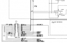
Here (for example) you can see the ribbon connector on the power board, in the section which drives the lamp rows:

1607017286650.png

You can see D0 on pin 28. Whenever LMP_ROW strobes, the 8 data bits (D0-D7) are latched into the 8 lamp rows. Same thing happen for the other addresses (e.g. SOL_1 which controls eight solenoids). These strobe lines are driven by the custom WPC ASIC by decoding the CPU address lines.

In this case, the fact that 2 things were broken which both depend on the D0 line is what led Andy to suggest checking that rather than power.
 
Last edited:
Hi @Fubar
Have you attached a picture, as I can’t see anything in the post.
Is this information in a WPC manual? I can’t see anything in the FS manual that shows the data lines.
Appreciate your help.
 
Thanks for that, after you posted the link in your new reply the picture appeared in your previous post. Bizarre!
Anyway, thank you again. Off to study the drawing 👍
 
Back
Top Bottom