What's new
Pinball info

Register a free account today to become a member! Once signed in, you'll be able to participate on this site by adding your own topics and posts, as well as connect with other members through your own private inbox!

First Partial Restoration (Royal guard)

Bandit Boy

Registered
Joined
Aug 18, 2015
Messages
671
Location
Wombwell, Barnsley.
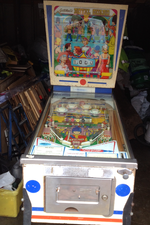
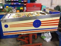
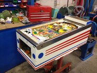
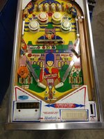
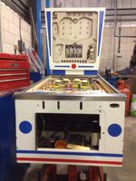
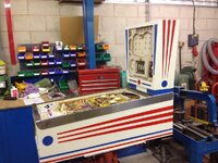
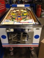
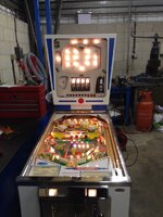
This is my first ever go at smartening up an old pinball, not confident enough yet to fully strip out but doing a nice new paint job.

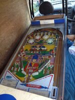
Collected in Combo Van.
i278.photobucket.com_albums_kk105_BarnsleyBrewer_Mobile_20Uploeb742ed4d79b1d7cb773030bb4aae4f3.jpg

Original Condition.
i278.photobucket.com_albums_kk105_BarnsleyBrewer_Mobile_20Uplo50023936d0496cb7a7c6992804b7b5c9.png
i278.photobucket.com_albums_kk105_BarnsleyBrewer_Mobile_20Uplo358a6becdbda32a1a0a20f19254879d6.jpg

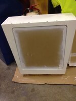
Filler and Sanding
i278.photobucket.com_albums_kk105_BarnsleyBrewer_Mobile_20Uplo14bf0918e259d207bc373ff3dca04b98.jpg
i278.photobucket.com_albums_kk105_BarnsleyBrewer_Mobile_20Uplo1e38d4b1135c9e2b7637e0602b96a980.jpg

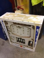
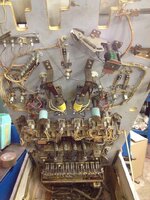
Under Playfield
i278.photobucket.com_albums_kk105_BarnsleyBrewer_Mobile_20Uplo4c724dced670393f71fadae4c6ee4a55.jpg

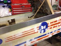
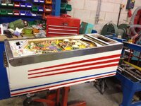
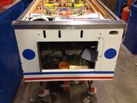
Painting Started.
i278.photobucket.com_albums_kk105_BarnsleyBrewer_Mobile_20Uplo9b81507828fc86d548134f444367804e.jpg
i278.photobucket.com_albums_kk105_BarnsleyBrewer_Mobile_20Uplocc3c3e5a8c0904951063e1a09493ef63.jpg
i278.photobucket.com_albums_kk105_BarnsleyBrewer_Mobile_20Uplo92ba43af323e3561b3b50f4bd2d410fd.jpg
i278.photobucket.com_albums_kk105_BarnsleyBrewer_Mobile_20Uplo1a43292eaaa38bb9dea67d790c496393.jpg

Gave playfield a good clean.
i278.photobucket.com_albums_kk105_BarnsleyBrewer_Mobile_20Uplo8b3eb2aa2d409b9ecdadf3873ea327a3.jpg

That's as far as I am... Great hobby and love of pin tables.
 
Can anyone tell me the size of the flipper rubbers please, looks like there's 4 that need replacing.
Also a good selection of fuses to buy for this machine.

Thx
 
Nice, how did you paint the shapes back over?
 
I'm earthing all the metal bits for safety and using a new 3 core power supply from the transformer..
Can anyone recommend the best way to do the new power supply?

1. Wire straight from transformer to plug
2. Wire to connector from transformer then to plug
3. Wire to new type bandit/pinball male to female connector with hole drilled in rear of cabinet with attachable flex.

BB ?
 
Last edited:
I do wonder, how important is it to earth those metal components on an old EM? I know there is risk from not earthing it, but I also think, how many people have ever had a life threatening pinball machine injury, or died from them?
 
I take it you've never played one of Andy Fosters older machines.
A shocking experience, literally.
 
I'm earthing all the metal bits for safety and using a new 3 core power supply from the transformer..
Can anyone recommend the best way to do the new power supply?

1. Wire straight from transformer to plug
2. Wire to connector from transformer then to plug
3. Wire to new type bandit/pinball male to female connector with hole drilled in rear of cabinet with attachable flex.

BB ?
I've read this a couple of times now, and still have no idea what you're asking.
 
I've read this a couple of times now, and still have no idea what you're asking.
Sorry,
The cable at the moment is an old twin core nasty bit of wire that needs renewing.
My thoughts are..... From the transformer do I just run a wire to the plug or is there a fancier way of doing it
 
I do wonder, how important is it to earth those metal components on an old EM? I know there is risk from not earthing it, but I also think, how many people have ever had a life threatening pinball machine injury, or died from them?
Just a worry when your kids are playing on it.
 
It's got metal and it's got mains. Earth it. No brainer. But I think you knew that ;)

It's a particularly good idea as you tend to grip pinball machines with both hands so if there was a fault you could end up sending the current right across your chest and stop your heart. Not so good. Also, if you ever wanted to take it to a public show it would never pass a PAT test without exposed metalwork being earthed.

To keep it original just replace the cable with some decent 3-core flex. At least 5A in whatever colour looks appropriate. Probably black rubber would look good and be hard wearing.

You could do an IEC C14 socket on the rear then use a PC-style power cable. Easier to put away when moving. You can also get C14 sockets with built in power switches, fuses, power on indicator lamp and/or built-in EMI filters. I don't know if filter are often fitted in old EM pins (they are internal on SS and DMDs)? Basically they suppress interference on the mains. Pinball machines with their clicky switches, solenoids and relays generate a lot of noise and an inlet filter stops it bleeding back out.

http://www.bulgin.co.uk/Products/Mains_Filters/Mains_Filters.html

Thanks' for that, a C14 that's just what I was after but didn't know what they were called to do a search.. :thumbs:
 
Had the chrome smartened up by a mate who works at a chroming place.
Has anyone got a spare plastic coin slot and coin chute I could buy?

i278.photobucket.com_albums_kk105_BarnsleyBrewer_Mobile_20Uplo940f22deae7314861b6eca10c6454297.jpg
 
Just had my first EM electrical belter......
I now know that just because the power switch on the base of the cabinet is off it doesn't mean the power is killed to all internal parts.....

Still not getting machine to reset??
 
Hi,

It seems to have re-set the score reels to zero; I'd imagine that those top lanes A to E meant to be lit at the start of a game, if so that control bank (probably under the playfield) has reset, if there's another for the targets/bumpers then that too. Next would be returning the ball counter unit to zero and serving out the first ball - Gottlieb e/m's don't enable the flippers and playfield solenoids until the ball count unit steps up to '1' (there's nothing lit on the card holder display). This occurs when the ball crosses a switch in the runway between outhole and ball shooter, so if the outhole solenoid isn't working or the ball isn't present the start-up sequence can't be completed.

Is the picture showing the m/c simply after switching on? Gottlieb (and the other u.s. manufacturers) e/m games usually didn't light up to that extent 'from cold' - Williams and Bally games had contacts on the left flipper button which would bring in the 'Hold' and/or 'Game Over' relay to make them more attractive, but Gottliebs would just sit with the 'Tilt' lamp lit until they were started up properly (or the Hold relay was pushed into contact manually). Maybe this one has the Hold relay jammed On.

Anyway, do you have the diagram for the machine? Gottlieb ones all seem to be drawn in the same format. The mains circuitry is bottom right, usually with the coin switches, Replay/Start button, start relay, etc.

Moving upwards, next is the transformer, with the 25v power for relays and solenoids on the right and 6v for lamps on the left. In the 25v section, the most important operating circuits are at the bottom, with the playfield devices at the top, cut off by contacts on the Tilt and Game Over relays (shown in the r/h vertical 'return') . Look for the solenoid winding marked 'outhole' or 'ball feeder'. The circuit connections for each relay, solenoid and disc/wiper unit are drawn left to right, including relay contacts and ones on the motor.
 
Last edited:
Back
Top Bottom