What's new
Pinball info

Register a free account today to become a member! Once signed in, you'll be able to participate on this site by adding your own topics and posts, as well as connect with other members through your own private inbox!

In Progress F14 project

stationfire

Registered
Joined
Aug 10, 2016
Messages
141
Location
Ireland
I have put off starting this one for a little too long, and as I had a question from another member, I thought "now is the time".

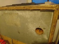
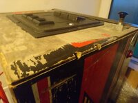
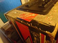
I don't have many pictures yet of the outside - here are some from when it was being moved.
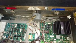
As you can see, cabinet art is terrible, but the wood itself is reasonably solid, needs plenty of filling, clamping etc before even starting on tackling paint/art etc. That's way off into the future - tackling the mechanical and electronic issues first...

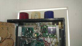
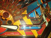
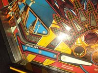
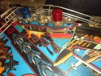
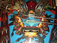
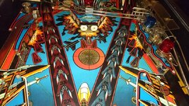
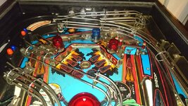
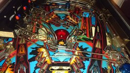
It's an early production one, so has the extra flashers on the top-right of the playfield, clear back flashers, clear centre beacon, and (unfortunately) the older display - more on that in the near future..

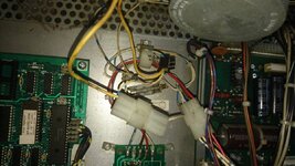
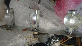
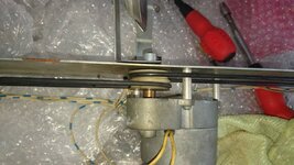
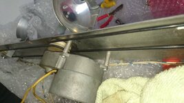
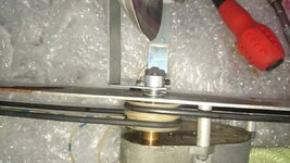
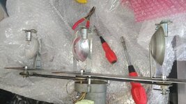
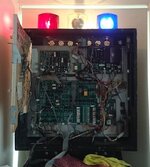
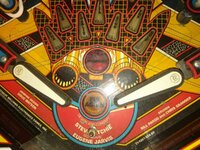
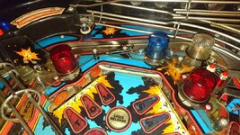
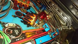
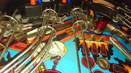
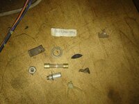
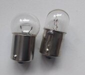
After the initial wiping and cleaning the inside of the cabinet a little (microfibre cloth and hand-helf vacuum only), I tackled the beacons. The belts missing and bulbs were both the wrong type and also blown, which isn't surprising as someone put 12v bulbs in there. That worked out nicely as you can see. The beacon covers need more cleaning but I'm quite wary that the plastic may have become brittle over the years, so may be safer not to do any more with them.
 

Attachments

  • DSC_1826.jpg
    DSC_1826.jpg
    90.6 KB · Views: 32
  • DSC_1827.jpg
    DSC_1827.jpg
    91 KB · Views: 33
  • DSC_1828.jpg
    DSC_1828.jpg
    97.7 KB · Views: 33
Last edited:
Here are some pictures of the beacon assembly. Initially I thought I should be removing the covers themselves, then take the motor off and sort out the belts, but that rapidly seemed like the wrong option. So, I cleaned the covers anyway, put them back on, then took the whole assembly off from inside the backbox. Easy enough, and someone seems to have done some work on this over the years with that connector block...

The motor is mounted on the wide sheet of metal with a series of metal cylinders as "standoffs" and 3 screws. Those remove easily... then you use your imperial size allen keys (a must) to remove the threaded screw/pin which is holding the motor to the centre beacon. Once that's done it's an easy task to clean things a little, add the belts, then add the motor back to the metal sheet and reconnect it to the centre beacon using that threaded pin.

Hopefully some of the pics may be of some help @PBrookfield - I can get you some more in the coming days if there's something specific you need.
 

Attachments

  • DSC_2205.jpg
    DSC_2205.jpg
    116.6 KB · Views: 23
  • DSC_2206.jpg
    DSC_2206.jpg
    107.3 KB · Views: 22
  • DSC_2207.jpg
    DSC_2207.jpg
    96.7 KB · Views: 23
  • DSC_2208.jpg
    DSC_2208.jpg
    80.7 KB · Views: 21
  • DSC_2209.jpg
    DSC_2209.jpg
    91.9 KB · Views: 23
  • DSC_2210.jpg
    DSC_2210.jpg
    109.8 KB · Views: 23
  • DSC_2211.jpg
    DSC_2211.jpg
    118.1 KB · Views: 23
  • DSC_2212.jpg
    DSC_2212.jpg
    89 KB · Views: 24
And here they are working. As you can see, the yellowing of the centre beacon isn't anywhere near as bad as some I have seen pictures of online.
 

Attachments

  • init_clean_beacon_working.jpg
    init_clean_beacon_working.jpg
    69.9 KB · Views: 28
Cheers for those photos of the beacon mechanism, they are actually pretty damn helpful. The whole thing is simpler than I imagined and I think I could fabricate all of the parts I needed if I get hold of the motor and the pulleys.
 
This might help also when you're fabricating- see the exploded diagram. I can grab measurements for you on specific items with calipers if needed @PBrookfield

https://www.tiltedpinball.com/tilted-pinball-shop/f-14-beacon/

The motors seem to be readily available in the US (marcos etc) - not ideal, and I reckon a bit more of a google search might locate one in Europe. Otherwise a wanted here maybe? I'm always surprised at how quickly things can be located with so many great people here on pinballinfo.
 
Just a few of the playfield before an initial wipe with a microfibre cloth...
 

Attachments

  • DSC_2040.jpg
    DSC_2040.jpg
    182.6 KB · Views: 24
  • DSC_2041.jpg
    DSC_2041.jpg
    193.4 KB · Views: 23
  • DSC_2042.jpg
    DSC_2042.jpg
    184.6 KB · Views: 24
  • DSC_2043.jpg
    DSC_2043.jpg
    168.1 KB · Views: 26
  • DSC_2044.jpg
    DSC_2044.jpg
    169.9 KB · Views: 23
  • DSC_2045.jpg
    DSC_2045.jpg
    166.7 KB · Views: 23
And some after - nothing more so far than the microfibre cloth wipe and a light handheld vacuum with soft brush. I won't clean further until I have plasics off for cleaning and re-rubbering. The inserts aren't bad and not faded like I have seen with others. Most of the markings on the decals are intact, so with the mylar over them I expect they'll lightly "novus" and wax (gerlitz wax) quite well. I'm not doing the mylar removal - it's just too much. The planking is unfortunate but I have seen so many torn up F14s on various forums I don't think this is at all bad.
 

Attachments

  • init_wipe_centre_top.jpg
    init_wipe_centre_top.jpg
    158.5 KB · Views: 15
  • init_wipe_playeifled_flippers.jpg
    init_wipe_playeifled_flippers.jpg
    168.4 KB · Views: 15
  • init_wipe_playfield_centre.jpg
    init_wipe_playfield_centre.jpg
    174.5 KB · Views: 13
  • init_wipe_playfield_top.jpg
    init_wipe_playfield_top.jpg
    156.8 KB · Views: 14
  • init_wipe_playfield_upper.jpg
    init_wipe_playfield_upper.jpg
    155.8 KB · Views: 14
The unfortunate consequence of not having any mylar at the top...
I would be interested to hear any ideas on how best to protect this and stop it getting worse.
I have considered perhaps having an artist friend touch it up in these specific areas, but I'm unsure - still has to be protected with something afterwards.
Any thoughts?
 

Attachments

  • init_wipe_playfield_wear_top_right.jpg
    init_wipe_playfield_wear_top_right.jpg
    150.7 KB · Views: 26
  • init_wipe_playfield_wear_top-left.jpg
    init_wipe_playfield_wear_top-left.jpg
    135.9 KB · Views: 24
No hidden cash in this one when cleaning out the cabinet. Here's my treasure trove gathered from various areas at the back of the cabinet...
ebay anyone? "rare original parts"
 

Attachments

  • DSC_2059.jpg
    DSC_2059.jpg
    153.2 KB · Views: 12
A grubby backboard.... then following a cleaning
 

Attachments

  • DSC_2025.jpg
    DSC_2025.jpg
    57.3 KB · Views: 17
  • DSC_2281.jpg
    DSC_2281.jpg
    57.4 KB · Views: 17
Spot the difference - clue: one of them is not the correct bulb for the backboard flasher. It is for a car... didn't stop someone popping it in there ("it fits, must be ok"). Somewhat like the 12v bulbs someone put in the beacons, which obviously blew.
 

Attachments

  • DSC_2282.JPG
    DSC_2282.JPG
    59.8 KB · Views: 21
One of the first things did was to check the fuses and ratings, make sure they were all the correct type per the tech chart. I'm rather glad I did, as 6 were the wrong rating. This wouldn't be so bad if they were slighty lower than the original rating, but how about 6A in a 4A? yes, had that for the flipper supply, as an example.

I found pretty bad corrosion on these fuse holders, but limited to only these. Had an order to go to CPC anyway, so added some chassis mount fuse holders and plenty more fuses for the parts supply. The fuse holders won't look the same, but they are rated correctly and for the correct size. These are so bad that the fuses are rarely getting a decent connection, so are for the bin. That explained the GI being out in a couple of areas but then working again intermittently after I checked fuses.

Check those fuses and ratings first folks!
 

Attachments

  • DSC_2195.jpg
    DSC_2195.jpg
    122.3 KB · Views: 17
Got the corroded fuse holders swapped out - pics to follow when I have time to upload from the camera.
The fuse holders from CPC did have pin/hole on the plastic base to allow them to be tehered/ "grouped" together for mounting, but I felt they were a little too close together compared to the original separation of the fuses, so I mounted all 4 separately in the same area as the original fuse holder. Popped in the new fuses, all good now with GI.

I also added a "special solenoid saver" board which I sourced from a pinside member - have a read up on these, they seem worth it given the add an extra diagnostic possibility, but most importantly an extra level of protection for the MPU board. Yes, you could make your own, but this has the connectors, cable, fuses included (need to use mainly 1A as opposed to 1.25A) for a reasonable price. Shipping from the US was $13 or so, but still reasonable overall.

I'll probably add one of Inkochitno's bridge boards in the near future also.

Anyone else go for the SSS board or bridge board? I'm pretty much just trying to ensure that I don't get hit by the very real issues that can occur, especially as I'll be rebuiliding the 4 flippers, popper and 1 sling.

All 4 flipper coils are also the wrong type (completely..). - again more pics to follow...
 
Pic is at a bit of an angle so things look a little slanted, but they're straight! - tidy up to be done on the cabling to the fuse holders with a velcro tie I expect. Would have been nice to get the exact spacing of the original 4-way fuse holder, but these are appropriately rated and definitely safer than the corroded ones that were in there.
You can see the SSS board to the right of the MPU board. With a much longer cable it could have gone on the side of the head, but I saw a pinside member had used this space (it's mounted about 1cm to the right of the MPU board), and I took a look and thought it made reasonable sense. Mounted it, triple-checked how it should be connected (board is designed for sys3-7, but works on sys11a also). Once I was sure, connected it, popped in the fuses and fired it up - all special solenoids still working, so now have that extra protection level (and will be less stressful as I'm working on the flipper, pop bumper and slingshot rebuilds. The single fuse sitting diagonally was like that when I started - figured it was far enough away and it meant that it gave a little extra clearance to the SSS board.
Have since grouped the cables together more cleanly and placed in the original cable hooks - this photo made it easier to see the SSS board.
 

Attachments

  • DSC_2255.JPG
    DSC_2255.JPG
    108.6 KB · Views: 22
@russdx1 sorry for the delay
Have a bunch of photos still to post as it's a lot further along after all new coils and flipper rebuilds. I will start some updates soon as I have done quite a lot of work.

I used naphtha and a microfibe cloth - tested on a small area first. Remove all bulbs first of course. It evaporates quickly so can't damage the fibreboard, but it cleans nicely (check pinside forums). Leave the cloth outside on concrete for a while to finish evaporating and it'll be reusable again - without a whiff of the naphtha.
I also use it on the playfield to be safe.
You'll get it as zippo or swan lighter fluid in your tobacconist. Be careful using it - ventilation, no flames or sparks
 
Back
Top Bottom