What's new
Pinball info

Register a free account today to become a member! Once signed in, you'll be able to participate on this site by adding your own topics and posts, as well as connect with other members through your own private inbox!

EM Pinball eject problem

Practicalpete

Registered
Joined
Feb 13, 2019
Messages
27
Location
Marske By the Sea
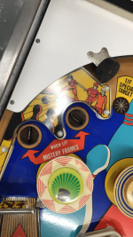
Hello, I am very much a newbie to pinball restoration and I'm looking for some help and advice please. I have a Nordamatic Champion EM pinball (1975- All the parts are Gottlieb),which I have now got working. However, when the ball drops into either of what I call a pocket (there are two of them one next to each other, see photo), it normally gets ejected after a short period. This happens most of the time but every now and again it doesn't get ejected. I have checked the contacts underneath the pocket and they are clean and making and breaking correctly. Unfortunately I do not have the schematic for this pinball. Look forward to any suggestions as to what the issue may possibly be? Regards. Peter.
 

Attachments

  • Nordamatic Champion.PNG
    Nordamatic Champion.PNG
    209.8 KB · Views: 8
Is the motor turning when the ball goes in the hole? If it is it could be a dirty motor switch as that is where the eject pulse comes from
Hello David, thank you for replying, the motor is turning continuously but the ball just sits in the pocket?
 
Hi Pete
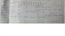
I don't have a schematic for Champion, but the following is from a Gottlieb Surf Champ
On here the circuit is relatively simple:
A ball in the hole closes the hole switch which activates the hole relay (I) - the green highlight
The hole relay has a switch which runs the motor for as long as the hole relay remains closed - the red highlight
The hole eject kicker is activated by a switch on the motor at position 4C closing briefly as the motor turns and through a switch on the hole relay which is closed whilst the relay is activated - the blue highlight
(The hole relay remains engaged through another switch on the hole relay itself until it is released by a normally closed switch on the motor opening - I didn't include all of that part of the circuit for clarity)

Given that the ball in the hole in your machine is running the motor we can assume the first two steps are working OK, so in my example the two areas you would need to look at are
1. The switch on the hole relay (I) which forms part of the circuit to the hole eject coil
2. The motor switch at 4C which forms part of the circuit to the hole eject coil
ie the two elements in the blue highlighted area

In fact on Surf Champ it is even easier, since you can see that the same motor switch feeds both the kickout hole on the playfield and the eject kicker in the outhole, so if the outhole was kicking ok I would know that motor switch was OK (or VV), but I'm not sure that would hold true for your machine

I would start by identifying the hole relay (look which one pulls in when the ball drops in the hole) and checking/cleaning/adjusting the switches on that
If that doesn't solve it you will need to find the motor switch.
Since you don't have the diagram you could try the following
1. There is often a chart stapled near the motor showing what each of the switches do - if that is present that will tell you which is the relevant switch
2. Trace the wires from the hole relay switches to the motor switches - if you have a multimeter with a continuity buzzer you could use this, or failing that look at the wire colours - either way that is going to long winded, hence the usefulness of a schematic!. To help, you can ignore any switches which are normally closed in the dwell position on the motor, and also those at the "impulse" level (ie operated by the jagged teeth) - on surf champ the motor switch is at level C which is the main top cam and easiest to get at
3. You could also ask other owners of the game on pinballowners.com if they have a schematic they might send you a photo of (or an extract) and also ask the same on pinside.com - there are a lot of very helpful people on there!

If you need to clean a motor switch remember that the motor can be pivoted 90 degrees by removing a hairpin clip if that makes it easier (assuming a Nordamatic is like a Gottlieb)

Hope that's helpful - it should be a fairly straightforward problem to solve I think

Do post on here when you get it sorted

David

1619940100493.png
 
Hi Pete
I don't have a schematic for Champion, but the following is from a Gottlieb Surf Champ
On here the circuit is relatively simple:
A ball in the hole closes the hole switch which activates the hole relay (I) - the green highlight
The hole relay has a switch which runs the motor for as long as the hole relay remains closed - the red highlight
The hole eject kicker is activated by a switch on the motor at position 4C closing briefly as the motor turns and through a switch on the hole relay which is closed whilst the relay is activated - the blue highlight
(The hole relay remains engaged through another switch on the hole relay itself until it is released by a normally closed switch on the motor opening - I didn't include all of that part of the circuit for clarity)

Given that the ball in the hole in your machine is running the motor we can assume the first two steps are working OK, so in my example the two areas you would need to look at are
1. The switch on the hole relay (I) which forms part of the circuit to the hole eject coil
2. The motor switch at 4C which forms part of the circuit to the hole eject coil
ie the two elements in the blue highlighted area

In fact on Surf Champ it is even easier, since you can see that the same motor switch feeds both the kickout hole on the playfield and the eject kicker in the outhole, so if the outhole was kicking ok I would know that motor switch was OK (or VV), but I'm not sure that would hold true for your machine

I would start by identifying the hole relay (look which one pulls in when the ball drops in the hole) and checking/cleaning/adjusting the switches on that
If that doesn't solve it you will need to find the motor switch.
Since you don't have the diagram you could try the following
1. There is often a chart stapled near the motor showing what each of the switches do - if that is present that will tell you which is the relevant switch
2. Trace the wires from the hole relay switches to the motor switches - if you have a multimeter with a continuity buzzer you could use this, or failing that look at the wire colours - either way that is going to long winded, hence the usefulness of a schematic!. To help, you can ignore any switches which are normally closed in the dwell position on the motor, and also those at the "impulse" level (ie operated by the jagged teeth) - on surf champ the motor switch is at level C which is the main top cam and easiest to get at
3. You could also ask other owners of the game on pinballowners.com if they have a schematic they might send you a photo of (or an extract) and also ask the same on pinside.com - there are a lot of very helpful people on there!

If you need to clean a motor switch remember that the motor can be pivoted 90 degrees by removing a hairpin clip if that makes it easier (assuming a Nordamatic is like a Gottlieb)

Hope that's helpful - it should be a fairly straightforward problem to solve I think

Do post on here when you get it sorted

David

View attachment 137473
Hello David, thank you for your detailed explanation and section of drawing. Luckily the wire colours are really good which makes them easier to trace, however, still quite laborious without a drawing. I will go through your description and let you know how I get on. May not be for a day or so but I will post back. Regards. Peter.
 
Hi Pete
I don't have a schematic for Champion, but the following is from a Gottlieb Surf Champ
On here the circuit is relatively simple:
A ball in the hole closes the hole switch which activates the hole relay (I) - the green highlight
The hole relay has a switch which runs the motor for as long as the hole relay remains closed - the red highlight
The hole eject kicker is activated by a switch on the motor at position 4C closing briefly as the motor turns and through a switch on the hole relay which is closed whilst the relay is activated - the blue highlight
(The hole relay remains engaged through another switch on the hole relay itself until it is released by a normally closed switch on the motor opening - I didn't include all of that part of the circuit for clarity)

Given that the ball in the hole in your machine is running the motor we can assume the first two steps are working OK, so in my example the two areas you would need to look at are
1. The switch on the hole relay (I) which forms part of the circuit to the hole eject coil
2. The motor switch at 4C which forms part of the circuit to the hole eject coil
ie the two elements in the blue highlighted area

In fact on Surf Champ it is even easier, since you can see that the same motor switch feeds both the kickout hole on the playfield and the eject kicker in the outhole, so if the outhole was kicking ok I would know that motor switch was OK (or VV), but I'm not sure that would hold true for your machine

I would start by identifying the hole relay (look which one pulls in when the ball drops in the hole) and checking/cleaning/adjusting the switches on that
If that doesn't solve it you will need to find the motor switch.
Since you don't have the diagram you could try the following
1. There is often a chart stapled near the motor showing what each of the switches do - if that is present that will tell you which is the relevant switch
2. Trace the wires from the hole relay switches to the motor switches - if you have a multimeter with a continuity buzzer you could use this, or failing that look at the wire colours - either way that is going to long winded, hence the usefulness of a schematic!. To help, you can ignore any switches which are normally closed in the dwell position on the motor, and also those at the "impulse" level (ie operated by the jagged teeth) - on surf champ the motor switch is at level C which is the main top cam and easiest to get at
3. You could also ask other owners of the game on pinballowners.com if they have a schematic they might send you a photo of (or an extract) and also ask the same on pinside.com - there are a lot of very helpful people on there!

If you need to clean a motor switch remember that the motor can be pivoted 90 degrees by removing a hairpin clip if that makes it easier (assuming a Nordamatic is like a Gottlieb)

Hope that's helpful - it should be a fairly straightforward problem to solve I think

Do post on here when you get it sorted

David

View attachment 137473
hello again David, I have tried lots of websites and forums asking for a schematic, no luck as yet, however, a chap called Frederico who replied to an email I sent to Tilt.IT in Italy said he has one but can't get to it due to their current lockdown?
 
I have my fingers crossed that Frederico can help me with a schematic, I originally contacted him through Tilt.IT I am looking to get back into the pinball tomorrow and keen to follow your description through.
 
  • Like
Reactions: DAD
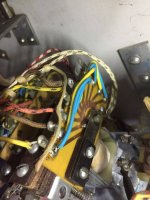
Hello David, finally sorted the problem of the ball not being ejected from the hole/pocket. Unfortunately the section of the schematic you sent me didn't match up with the circuit on my pinball. Eventually after a few hours of tracing cables etc, I found a contact on the unit in the photo was catching on a small rivet head to the side of it, I adjusted the switch body with away from it and it's now working ok. Thank you again for your help with this. Regards. Peter.Champion Pinball.JPG
 
Hello again David, at the risk of being a pest, could you please send me a photo showing the circuit for the chime unit. For some unknown reason someone has taken the original chime unit out.?I have bought an old Friedland door bell, the solenoid "ding dong" type.
Regards.
Peter.
 
is it a 3 bar chime bar? ie if it is then you’d have 4 wires. a common and three control wires one of each chimes. 10, 100, 1000 points. not sure though on these earlier machines?
 
Hi Pete
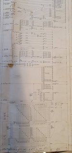
I've attached the schematic extract you asked for, but I'm not sure how useful that is
If your game is wired similar to a Gottlieb, each chime will be operated by a switch on the respective score relay, so the 100's relay will have a switch to operate the 100's chime, and so on.
If there was a chime box that someone has removed, you should find the wires hanging near the front door - as Alan has said there will be a common wire and one for each of the chimes. The common will be the same colour as for the return on all the solenoids - on surf champ it is black but Nordamatic may have used something different
If you can't find an original replacement you can buy a repro unit here: https://www.chimeunit.com/chime-units

EDIT - just realised the photo is no use at all as Tapatalk has reduced the image size and it is no longer legible when enlarged. If you do still want it, PM me your email address

surf champ chimes.jpg
 
Hello David, thank you for the explanation of where the chime units receive their signals, I have found the wiring fr them, it had been pulled back along the harness and taped up . Thanks for posting the schematic but not needed now. Really appreciate your help with this David.
 
is it a 3 bar chime bar? ie if it is then you’d have 4 wires. a common and three control wires one of each chimes. 10, 100, 1000 points. not sure though on these earlier machines?
Hello Alan J, thank you for your reply, it was originally a three chime, I have since found the wiring for it.
 
Back
Top Bottom