What's new
Pinball info

Register a free account today to become a member! Once signed in, you'll be able to participate on this site by adding your own topics and posts, as well as connect with other members through your own private inbox!

Eight Ball Deluxe Solenoid Issues

2huwman

Registered
5Years
Joined
Sep 6, 2015
Messages
61
Location
Isle of Wight
I picked up an 8BD locally, in generally reasonable shape. While I'm waiting for the playfield hardtop to arrive, I want to try to fix a few solenoids that aren't firing. This is my first attempt to repair a pin, so I'm open to all suggestions, no matter how basic!

I've been following an online guide, so I feel like I've made a little bit of progress in trying to figure out what's wrong: https://homepinballrepair.com/troubleshooting-early-bally-and-stern-pinball-machines/#solenoids

The solenoids that don't fire are for the outhole kicker, the 4 drop target reset, and the saucer. All others seem to work fine when play-testing, although the right bumper one is slow to reset. Here's a video of the self test:

8BD Solenoid Self Test

Looking at the manual, tests 16, 17, and 18 should relate to the solenoids that aren't working, but it's only tests 19 & 20 when there's silence. So either the manual is wrong or there's some crossed wires somewhere!

I've measured all the solenoids and the non-working ones all have resistance readings consistent with the working ones, given their various different sizes. They are also getting the right amount of current when a game is started.

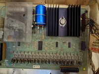
Here's what the solenoid driver board looks like:
PXL_20221114_170746848.jpg

I've tried shorting all transistor tabs to ground as suggested in the above guide, and the only 3 that don't fire are labelled Q15, Q17, and Q19 on the PCB. These are the 3 that don't work when playing, but again don't tally with the manual. There's also no transistor in position Q18 on the PCB, so not sure if this is also a problem.

So is it likely that the Solenoid Driver Board is the culprit? either the transistors, the header pins, plugs, or some of the wiring coming into it. It looks like the long connector on the top right has been chopped and replaced, which might explain why the self-test isn't consistent with the manual.

I'm tempted just to buy a repro Alltek Solenoid Driver PCB, but don't want to damage that if there are other problems. Also repairing the SDB should be within my soldering abilities if I know what to do.

The previous owner put a replacement Alltek MPU board in and that all seems to be fine.

Am I on the right tracks? Any help or suggestions would be much appreciated. Thanks!
 
Hello, Rich,

Transistor Q15 on the solenoid driver board is always used for the flipper relay, it's hard-wired on the circuit board. Grounding the tab of that should see the relay switch On.

Eight Ball Deluxe has a slightly more complex set-up for solenoids than many of the early Bally games. Because there are so many different solenoids, there's a 'Solenoid Extender', basically a glorified relay added under the playfield. It switches between two groups of solenoids, so that some of the drive transistors can be used for two different solenoids. The one I remember from this game is Outhole solenoid, which is 'doubled' with one of the target dropper coils, No.1 I think. I could see when looking at that case that the dropper was pulsing instead of the outhole when the game was trying to serve the ball out, and found cracked soldering on the Extender pcb.

Bear in mind that the number shown on the display(s) when pulsing a solenoid in the test isn't necessarily the number of the transistor actually being used. As far as I recall, Bally didn't adopt that convention, though Stern did, for the later games.
 
Last edited:
  • Like
Reactions: DRD
Hello, Rich,

Transistor Q15 on the solenoid driver board is always used for the flipper relay, it's hard-wired on the circuit board. Grounding the tab of that should see the relay switch On.

Eight Ball Deluxe has a slightly more complex set-up for solenoids than many of the early Bally games. Because there are so many different solenoids, there's a 'Solenoid Extender', basically a glorified relay added under the playfield. It switches between two groups of solenoids, so that some of the drive transistors can be used for two different solenoids. The one I remember from this game is Outhole solenoid, which is 'doubled' with one of the target dropper coils, No.1 I think. I could see when looking at that case that the dropper was pulsing instead of the outhole when the game was trying to serve the ball out, and found cracked soldering on the Extender pcb.
Thank you Jay - that would make sense in terms of what I'm seeing in the self test, wouldn't it (7x drop targets firing again instead of outhole, saucer, and 4x drop targets)? I'll have a look at that extender board. I did notice it under the playfield but didn't investigate further.
 
I've just looked at the manual on-line, the solenoid driver page in the section of the "yellow pages" shows the saucer and 7-target reset are driven from Q8, so there could be two pulses if the extender isn't working (one for the target reset 'proper', then again when it should be the saucer, test sequence numbers 15 & 17 respectively). The outhole and target 1 (&9) dropper use Q13 (sequence 18 & 08), and the in-line target reset and the dropper for target 2/10 share Q14 (sequence 16 & 09). Q18 isn't used for this game, so the missing component isn't a problem.

So, going by the Playfield Wiring diagram, the solenoids comprising the extender network are three 'pairs' - outhole and dropper 1/9, in-line (4 bank) reset and dropper 2/10, saucer and 7 bank reset. That's not as many as some games, f'r instance M&M Pac-Man.

Incidentally, as is more often the case than not, the solenoid board originates from a different game, Flash Gordon No. 8972.

I've also refreshed my memory of how the expander itself is controlled; it's switched as a lamp drive, from the lamp driver board, Q54.
 
Last edited:
I've just looked at the manual on-line, the solenoid driver page in the section of the "yellow pages" shows the saucer and 7-target reset are driven from Q8, so there could be two pulses if the extender isn't working (one for the target reset 'proper', then again when it should be the saucer, test sequence numbers 15 & 17 respectively). The outhole and target 1 (&9) dropper use Q13 (sequence 18 & 08), and the in-line target reset and the dropper for target 2/10 share Q14 (sequence 16 & 09). Q18 isn't used for this game, so the missing component isn't a problem.

So, going by the Playfield Wiring diagram, the solenoids comprising the extender network are three 'pairs' - outhole and dropper 1/9, in-line (4 bank) reset and dropper 2/10, saucer and 7 bank reset. That's not as many as some games, f'r instance M&M Pac-Man.

Incidentally, as is more often the case than not, the solenoid board originates from a different game, Flash Gordon No. 8972.

I've also refreshed my memory of how the expander itself is controlled; it's switched as a lamp drive, from the lamp driver board, Q54.
Thanks, that's great information. Incidentally (or maybe related) the fuse for the lamp driver board (on the main power board in the base of the cab) was blown when I got it, so I replaced it and the playfield lights started working. The fuse hasn't blown again, but replacing it didn't make any difference to the solenoid problems.
 
Another thing I hadn't recalled is that the expander pcb has a lamp socket wired alongside under the playfield. As I understand it this provides a proper load for the lamp drive circuit, rather than just switching the little chip on the expander pcb. The lamp failing can cause extender problems by itself.

The tiny chip is driven as a lamp load, but switches the extender relay, using the 43v solenoid power. Why make things easy? The comparable Williams expander set-up uses a solenoid drive to control the relay, keeping things 'in-house', so to speak.
 
put game in self test - first one is all lamp test - you should hear the solenoid expander relay click on and off - if not then check the light under playfield next to it is flashing on and off (if it is then the expander board is at fault) if it isnt, replace bulb, if still doesnt work - then look at the SCR on the lamp driver baord that is supposed to control it.
 
Thanks very much guys, this has been really helpful. I won't get a chance to have another look at it til next week as it's in my unit, so will try your suggestions and report back then.
 
check for cracked solder joints on the header pins of the driver board as well,Ive had that cause an issue in the past
 
Having overcome my antipathy to YT to look at your games' actual symptoms, the sequence seems to be okay as far as popping down all seven 'ball' targets, then resetting them. Then should come the three absent solenoids, 4-bank, saucer and outhole. but the alternative loads repeat, i.e. dropper 2, 7 bank reset, dropper 1. The thing is that going by the schematic, the extender relay connects the group you have working when Off, and the other (arguably vital for play, in the case of the saucer and outhole) group when On. So I'd concur with Alan and Steve that the extender doesn't seem to be working, has burnt contacts, or broken solder connections.

Sequence items 19 and 20 are the low-powered coin lockout on the front door and the flipper relay. Holding in the flipper buttons while 20 passes through should see the flippers kick slightly as the relay operates. These last two solenoid loads are controlled differently from the others; each has its own individual controlling line from the Mpu board, but they're routed via J4, rather than the larger J3 which you point out has been damaged/repaired.

If necessary, I think that it should be possible to operate the solenoid expander relay via the lamp driver board by making use of the lamp driver boards' test points. Any of the scr's on the lamp board can be switched safely by using a wire from TP 3 to apply 5v to its 'Gate' terminal*, switching it on independently. It's more usually used to check if a lamp isn't lighting due to poor wiring or a corroded bulbholder, but it ought to apply for the solenoid extender too.

* the picture of the lamp driver suggests that Gate of the larger '106' Scr is the lower terminal as seen with the board mounted in the backbox.
 
Last edited:
Thanks very much. Just a quick update - I managed to have a look at the Solenoid Extender this evening. I took the bulb out and it looked fine, so just put it back. I also unplugged the connector and cleaned the header pins. When I turned it on again the three previously unresponsive solenoids worked! The self test now functions properly and the game is playable! I didn't have long to test it, but noticed that the 4 bank solenoid seems to be a bit weak, as it usually only pushes the drop targets up part way. But the saucer and outhole are working now.

So thanks again for directing me to the solenoid extender. I'll test it some more later this week, but that seems to have been the issue.

Is the solution for weak solenoids just to replace them with new ones of the same size?
weak solenoid. it’s mechanical. they can get gunked up. take apart clean all the bits make sure plunger moves freely.
 
Assuming that it's the listed part, replacing a solenoid winding is a long way off when looking at a weak action. There may be something worn in the target mechanism, or some fool may have oiled the coil plunger, making things worse long term.

Also, being an 'expanded' solenoid, the bank reset will be a special coil; there's no difference with the actual winding from any 4-target reset, but the expander network requires additional diodes to separate the two loads (i.e. to prevent both sides or other branches of the network operating at the same time). Bally placed the diodes on the coils themselves, with a third terminal on the plastic former of each coil.
 
Last edited:
Thanks both, I've done a bit more reading and will clean the housings/sleeves on the weak ones. And I definitely won't oil them! It's great being able to play it so thanks for your help so far. Still a lot to do but a really nice winter project.
 
Had some more time to work on it yesterday. The Solenoid Extender works intermittently, so I've removed it and will resolder the header pins and see if that fully solves it. I cleaned up the coil mechanism and sleeve for the right slingshot and it resets much quicker now. Maybe not quite as quickly as the left so I might replace the sleeve, but it looks like I'm on the right track.

I managed to get a new Outside Edge 'Hardtop' via eBay for about £310 delivered, so once everything is working properly mechanically, I'll move on to fitting that. Thanks again for all the help so far.
 
Back
Top Bottom