What's new
Pinball info

Register a free account today to become a member! Once signed in, you'll be able to participate on this site by adding your own topics and posts, as well as connect with other members through your own private inbox!

Dr Who Dalek Topper

Doug Smith

Registered
Joined
Aug 5, 2011
Messages
13
Hi folk.

My DrWho has a moving dalek topper. Well, it is supposed to. It stopped moving some time ago.

It's not one of the more modern servo mods, it uses a DC motor and gearbox. it is definitely not an original one, because it connects via a set of piggy back plugs, but it may well be closely related to the prototype ones.

There is a resistor in series with the motor. I'm assuming this is a current limiting resistor so that if the DC motor jams it doesn't burn out the motor coils, or maybe it just slows it down a bit, or both.

However, the resistor was covered in shrink tube and has gone rather crispy.
It still meters a resistance, 5K ohm, but it's not looking healthy.
V=IR, so max current for 20v input would be 20/5000 = 0.004A - not enough to run a motor.
Plus the size of the resistor looks like it should cope with multiple watts so I'd expect significantly more current than that.

Any clue what spec resistor to use? I've had a look in the DrWho manual and there is nothing about motorised daleks in there...

Cheers,

Doug.
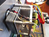
DrWhoDalekResistor.jpg

Phwoor, look at the size of them thar alooominimum angles...
 
Motor resistance measures 6 ohms.

I'm going to assume that the motor gets 20v (Assuming because I can't reach it when the head is up, so it's hard to check)

I'm going to assume that the motor actually wants to get 12v, so we drop 8v across this resistor.

This means the series resistor ought to be 4 ohms.
Total motor+series resistance of 10 ohms, meaning 2A total when it is running.
Series resistor is dropping 8V, which means it consumes 16w - which seems an awful lot....

I guess I'll have to check my supply of ceramic resistors!
 
I did have the details about the topper on a very old hard drive. Let me have a look tonight.
Can not promise, I may of wiped it off to expand my porn collection... oops - sorry music mp3 collection.....
Will post if I can find.
 
Thanks, all assistance is appreciated.

I did find This Page which gave a bunch of info on the prototype. It looks like mine follows the prototype closely, but is a small production / homemade one. There are differences - for instance there is one PCB for the opto and motor connectors.
 
Its not working like the proto one unless you have the prototype rom with the settings for the topper. Take the PCB and take some pics.

Sadly in my archive I do not have the pcb layout for the a-15818, and I can not find the photos of my prototype Dalek.
 
It is a working mod which stopped working some time back.
There are no issues with rom versions or anything like that. The test options are there in the menus, and in fact, it reports that the head isn't working on startup tests.

I double checked that the motor was running freely - clipped the remote battery box to the motor wiring and it turned, albeit rather slowly, as expected. So mechanically fine.

I shorted across the fried resistor, and the head made the small movement to centre as expected when I turned it on.

So, everything works, apart from the pictured series resistor, which is so badly crisped that I've got no clue as to what value and wattage it should be.

I'm guessing that the fried one wasn't an appropriate spec to start with. I assume that it lasted a long time because the head isn't moving that much, so the resistor had time to cool down.

I've made a guess as to what it should be, and I'll stick an appropriately sized one in there, but it is way more chunky than it should be...
 
If your motor is running slowly without a resistor then I’d suggest the gear box may be a problem. I’d take that apart and grease.
How many bolts is the motor ? What voltage is supply? Put your meter in series and see it to amps. See what it is pulling.
 
Hi Doug,

Pretty sure you got this game from me (swap for A13 if memory serves)? I believe I installed the kit, I'm certain it was this one

http://www.pinballobsession.com/PDFs/Wobble10a.pdf

Hope there's something useful in there


Yes, you are bang on. I've still got it and the missus would kill me if I ever thought of getting rid of it.

Thanks a million for the links to the manual for the kit. In the troubleshooting section, it says...

If your head is not centered as much as you would like, I would suggest replacing the 10-ohm resistor, heat shrunk to the red motor wire, with a larger (20 ohm) 2 watt resistor. This may improve you head centering. Keep in mind that the voltage to the head motor is fed from an unregulated supply, and this too adds more variables to obtaining the perfect wobble from the head on your machine. The 10 ohm resistor added what seemed to be the best “all around” value to slow the motor slightly for general use.

2W seems rather light for the crrent, I think I'll stick higher wattage rresistor in ther just to be on the safe side.

Thanks for the help!

Doug.
 
Back
Top Bottom