Hi fellas.
On my GNR the sound was all flaky, it would come and go. The volume control is by a physical stalk on the metal box inside the door, so by physical hardware rather than by software.
I did some research and got some leads which I worked through one by one:
-I did a factory restore in case the RAM was corrupt.
-I removed and reseated the four sound ROM chips on the sound board, as two of them were giving no sound in test mode.
-I checked and secured the wires attached to all three speakers, which are wired to CN4 on the sound board.
-I replaced all the connectors to the soundboard and a few others that looked crispy on the CPU board.
-I wanted to replace the 20-pin ribbon cable that goes from CN21 on CPU to C1 on the sound board, but don't have one so that will have to wait.
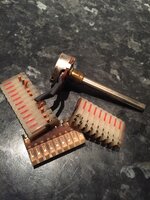
-I replaced that volume stalk 'trimpot' voltage potentiometer which I found was directly connected to CN3 on the sound board.
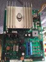
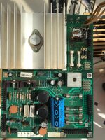
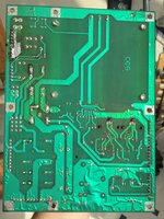
-Finally I found a smoking gun when I tested the voltages coming from the power supply board. +5V was perfect at 5.06V (4.99 on the CPU board). -12V was ok (I assume) at -13.5V. But the +12V was only 9.3V. Is this my culprit?
http://mirror2.ipdb.org/files/1100/Data_East_1994_Guns_N_Roses_Schematics.pdf
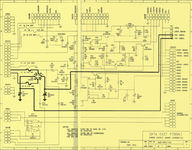
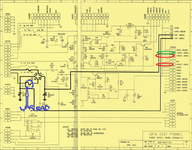
Does page 32/33 (p79/80 in the bottom right corner of the page) of this schematics document tell what and where the problem may lie?
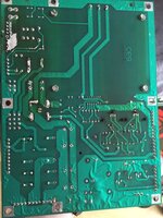
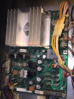
Where physically on the board do the components sit that I need to test/replace? Presumably I am looking for a knackered capacitor or bridge or diode or something?
Is it that massive frig-off huge thing top left with a humongous heat sink on it .... or the small grey square bridge to the bottom right of it ..... or one/some/all of the capacitors?
Cheers guys
On my GNR the sound was all flaky, it would come and go. The volume control is by a physical stalk on the metal box inside the door, so by physical hardware rather than by software.
I did some research and got some leads which I worked through one by one:
-I did a factory restore in case the RAM was corrupt.
-I removed and reseated the four sound ROM chips on the sound board, as two of them were giving no sound in test mode.
-I checked and secured the wires attached to all three speakers, which are wired to CN4 on the sound board.
-I replaced all the connectors to the soundboard and a few others that looked crispy on the CPU board.
-I wanted to replace the 20-pin ribbon cable that goes from CN21 on CPU to C1 on the sound board, but don't have one so that will have to wait.
-I replaced that volume stalk 'trimpot' voltage potentiometer which I found was directly connected to CN3 on the sound board.
-Finally I found a smoking gun when I tested the voltages coming from the power supply board. +5V was perfect at 5.06V (4.99 on the CPU board). -12V was ok (I assume) at -13.5V. But the +12V was only 9.3V. Is this my culprit?
http://mirror2.ipdb.org/files/1100/Data_East_1994_Guns_N_Roses_Schematics.pdf
Does page 32/33 (p79/80 in the bottom right corner of the page) of this schematics document tell what and where the problem may lie?

Where physically on the board do the components sit that I need to test/replace? Presumably I am looking for a knackered capacitor or bridge or diode or something?
Is it that massive frig-off huge thing top left with a humongous heat sink on it .... or the small grey square bridge to the bottom right of it ..... or one/some/all of the capacitors?

Cheers guys

