What's new
Pinball info

Register a free account today to become a member! Once signed in, you'll be able to participate on this site by adding your own topics and posts, as well as connect with other members through your own private inbox!

Complete Cosmic Gunfight

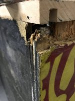
Most urgent issue is to deal with the damage to the backbox, 1/2 of the base panel has rotted away and there is also the dreaded woodworm. Rot also in the lower inch or two if the right hand side panel and also into the back panel.

My rule on woodworm, is deal with it immediately! Dont want those F******s getting into anything else.

IMG_8414.JPGIMG_8415.JPGIMG_8416.JPGIMG_8417.JPG

So it is outside for some radical remedial work:
IMG_8420.JPG
IMG_8421.JPG
IMG_8422.JPG
the far end of the base is solid and worm free, so I have left it to help keep the integrity of the frame together and also gives me a good reference point to work to when replacing the wood. Found a bit of MDF that will do the job.

IMG_8425.JPG
Cut a hole out - needs squaring up!


IMG_8426.JPGIMG_8428.JPG
cutting out the weetabix like wood from the side.

IMG_8429.JPG
ronseal wood filler


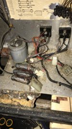
I stripped the backbox, but before I did - took plenty of pics:
6B2B2B91-36FA-401C-9420-81B3FABDB0E4.jpgIMG_8360.JPGIMG_8362.JPGIMG_8363.JPGIMG_8378.JPGIMG_8379.JPGIMG_8382.JPGIMG_8383.JPGIMG_8384.JPGIMG_8385.JPGIMG_8388.JPGIMG_8389.JPG

Electronics wise:
1. CPU board there and looks pretty clean, no hacks and no battery damage, so will test later to see if it boots
2. Rectifier board - looks a bit nasty - burnt connector that's been soldered, some dodgy capacitors - will test on bench and see if I can get it going
3. Sound board - looks ok - again worth a try
4. Driver board - missing, so sourcing one of those.
5. Display driver board looks ok and so do the displays, all need testing.
6. Transformer in the bottom cab - looks ok - needs testing.

Playfield looks really good, and no woodwork, cant see any in the main cab either.

Mechs on underside of pf all there, looks like a flipper has been raided for parts and there is a plunger and arm missing off one of the drop targets (that could be hard to find a spare - might need a whole new unit??

Coin door is rusty and horrid, legs are too.

Backglass is gone completely. I can get a new one made, mirrored or non? Hmm - I'll leave that decision until I get to the end of this project.
 

Attachments

  • IMG_8427.JPG
    IMG_8427.JPG
    73.9 KB · Views: 4
  • 73A12EB5-8618-4BBD-A169-614DDA394DBB.jpg
    73A12EB5-8618-4BBD-A169-614DDA394DBB.jpg
    114.5 KB · Views: 4
Bit of tlc and she'll be right as ninepence.
 
Cleaning up the back box metalwork

before:
C78074D2-5AC9-47D0-8C1C-A0AB23D2E520.jpeg
after a simple wash and scrub
909646DC-0E27-4391-8684-601A1C602E18.jpeg

meanwhile :
more filling of the woodwork
B1525EDB-6625-4E12-9FBD-BBDF8467C560.jpegB1525EDB-6625-4E12-9FBD-BBDF8467C560.jpeg

and squaring off the cutout, bit more to do still.
BDB8C92F-E7D4-43E5-935D-346790BAC07C.jpeg

Hoping to get the back box prep finished tomorrow.

That’s enough for today.
 
a lot more work than i realised. whilst i had the plastic wood going, decided to sort out the other corners and other knocks and scrapes

724E7FF3-E1A3-4E25-A6C9-79B8832366CF.jpeg02F305BA-3605-4035-9C35-2988F2AF6744.jpegDC511C3F-F926-4436-85A0-349927A3AA9B.jpegB8039F0D-CB87-4F57-81F0-53B1B5431732.jpeg835AC9B2-5B2B-43EE-9137-0BB81BE61117.jpegA20AC61B-EB5C-420C-B576-D9D728A07D87.jpeg
can be frustrating working right on the edges, as one wrong move whilst sanding can nick the edge off again. tried making a stronger mix, which seems to strengthen a lot better, but has a short work time!
 
what parts are missing from the drop target mech?,do you have a photo,I see there is a 1 bank williams drop target on ebay,that uses the same plunger as the 3 bank ones on my gorgar(system 6),or does system 7 use different mechs?
 
Hi thanks. it’s the plunger and then the plate the plunger connects to that lifts up the 3 drop targets. so it’s like a 3 pronged fork thing. I’ll post a pic
 
Last edited:
the plunger is the same as that one on ebay,it's just the plate that's different I believe
 
Not done anything on this apart from shell out £££'s and gather together new parts and used replacement parts. Been busy with other projects, but will get back on this next week.
 
Got a bit of time today to start putting the back box back together.
ED8E9999-12AE-4197-BB39-D8FEE44E0EDB.jpeg
1546D945-94C0-4E3C-A14C-A183A134D410.jpeg

E871D65C-F84C-4302-8E1D-11E0D74B9BC5.jpeg
Most of the wiring was disconnected when I got this machine. so a bit of a jigsaw puzzle to figure out what goes where.

Also got a new bridge and capacitor board and the original ones are well shot.
4E07D215-43CA-420B-A761-DF621A06FF93.jpeg
C37A2945-DB2D-4758-AB6A-F604E79F0930.jpeg
5AB500AB-3B59-4EF1-990C-DD1D855CD0A3.jpeg

Also bought a Special Solenoid Saver fuse board kit, so that needs building and installing.

Quite a unique connector arrangement from the mpu board to the driver board. they plug into each other on a 40 way 3.96mm pitch header and pcb socket. Not a fan of these. I’ll probably have to take it all out and carefully check all those 40 connections.
 
I have a spare 40 pin header kit for the driver board if you need it,happy to sell it for what I paid £10 posted
 
D52F25E1-91D5-4C90-B48D-25A08EC4C09C.jpeg
I’m going to have to figure out what sequence these need to be in when I put them back into a molex housing. I’ve got the schematics, so it should be in there.
 
before you go trailing through schematics,it's sometimes worth using google to look for images of an open backbox,you can sometimes zoom in on the connectors and see the wire colours if the image is clear enough
 
What's the solenoid saver do ?
Its a fuse board - 6 fuses sits between the Driver board and the 6 Special solenoids. These can easily burn out if a switch gets stuck as they are directly wired to the switch, so this protects that.

https://nvram.weebly.com/repair--conversion-kits.html

IMG_8597.JPG
Excuse the spaghetti wiring - I havent cable tied them yet. I'm just figuring out where everything goes:

IMG_8599.JPG

I also put in Peters Inkochnitos bridge rectifier board:

IMG_8598.JPG
It replaces the two rectifiers and the huge capacitor
https://home.kpn.nl/p.koch3/bridge_board.htm
 
Crimps arrived to sort out the loose wires to the power board
9DC31BAF-23C6-4F46-8EA2-8548CFF4D3CE.jpeg
FFB5B0BB-578C-4EBE-B25D-E4188219CBEB.jpeg

I need to find a shooter rod and the shooter rod housing plate. it’s all missing.

Tomorrow or Fri , I’ll switch on and test the mains transformer, then the power rectifier board.
 
I unplugged all the board and started slowly - first plugged in the new bridge rectifier board - made sure the 2 dc voltages were ok - they were.
2. Plugged the new bridge rectifier board into the main power supply board and tested all the voltages. All OK - getting +5, +12, + and - 110 for the displays. Looks good
3. Plugged in the AC 6.3V - all good too
4. Plugged in the power to the sound card - now get a speaker hiss when power up - so that's ok too.

Then moved on the trying to get the MPU to boot. First attempt - noting at all.

Checked the +5v on the mup board - its negligable.

So, I unplugged MPU and tried the display controller board - same thing the 5V drops off to around 1v.

I tried wiring an old incandescent 6v bulb to the 5v out of the Power board - nothing, again the voltage dropped to near zero.

With nothing connected it measures 5v fine, but as soon as I put any sort of load on the 5v line, it just collapses.
I suspected the 2N6057 - so swapped with one off another board that does give +5v ok (but has other issues, so don't want to use it). Same issue - the 5v collapses as soon as it's loaded up.

Anyone got any ideas please?

Ive changed the capacitors in the 5v circuit, so not those.
 
just an idea!,if you disconnect the 5v pin from the power supply board,have you got another 5v power supply source,you could feed the mpu 5v pin with?,if you have and it boots,you know it's a power supply issue.
 
Got the MPU Board on the bench - +5V and +12v applied - it shows an 8 on the 7 segment display, this after a number of seconds changes to a zero. Apparently it should go out? so not sure whats up with the board.

I tried the advice on pinwiki - temp jumper 8 and 9 TP's to see if its the reset circuit - it makes no difference.
 
does leons test rom work in a system 7 mpu?,I know it does in a system 6
 
just an idea!,if you disconnect the 5v pin from the power supply board,have you got another 5v power supply source,you could feed the mpu 5v pin with?,if you have and it boots,you know it's a power supply issue.
See above - its deffo the power board. I have the MPU out on the bench now.

Ive also plugged in the original power supply board and bingo the 5v works fine. I may clean up the rest of this one instead. (It needs some work!).
 
As suggested on Pinwiki - I added the 2 diagnostic test LEDs. When I apply power they both light and stay on, pressing the diag switch has no effect.

I guess this is just not booting at all.

It says it could be a 5101 Ram error, but I dont think it's even booting. Board looks nice and clean, no replacement parts, no hacks. Not sure where to start with this.
 
Sounds like either the BR or your power transistor is failing under load. I don't think there is much you can do other than test or replacing every component in the circuit starting with the BR and the 2N6057 (get a new one).

Easy enough to swap the RAM with a known good one to rule that issue out.
 
Thanks Peter. the 6057 has been replaced. i tried one i know works and it’s not fixed it, so I’ll try the bridge rectifier next as i have some spares.
 
Back
Top Bottom