What's new
Pinball info

Register a free account today to become a member! Once signed in, you'll be able to participate on this site by adding your own topics and posts, as well as connect with other members through your own private inbox!

Connectors to Rectifier board? Bally Strikes n Spares.

Ed209

Registered
Joined
Jul 19, 2019
Messages
25
Location
Ramsgate
Hey All,

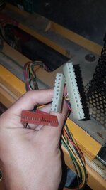
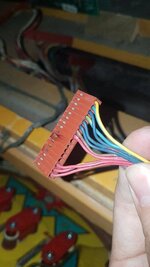
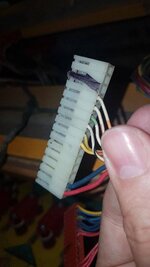
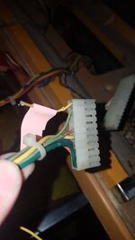
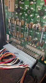
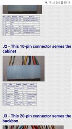
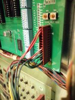
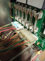
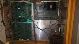
I've followed the power cable into the machine and after the surge stopping box the cables run off to three different connectors. I assume that two of them are meant to go on the J2 spot on the rectifier board in the backbox (photo attached). Unfortunately there are three connectors and they don't appear to correspond to the pins available on the rectifier board. Also the connectors seem to have a lot of blank slots, one of the wires has snapped and I'll sort that. This was one of Dave Rolfes machines so I'm guessing its something obvious that I am not getting as this is my first pin.

Cheers
Ed
 

Attachments

  • pinball_connector_02.jpg
    pinball_connector_02.jpg
    62.2 KB · Views: 19
  • pinball_connector_01.jpg
    pinball_connector_01.jpg
    52.9 KB · Views: 17
  • pinball_connector_03.jpg
    pinball_connector_03.jpg
    42.7 KB · Views: 18
  • pinball_connector_04.jpg
    pinball_connector_04.jpg
    41.7 KB · Views: 19
  • rectifier .jpg
    rectifier .jpg
    104.1 KB · Views: 20
I took my strikes and spares to pinfest, so I'll be setting it up sometime this week if you can hang on?
 
I took my strikes and spares to pinfest, so I'll be setting it up sometime this week if you can hang on?

Amazing! I get 5 minutes a day to tinker so I will not be doing much at all anyway! thanks Arv!
 
Hello, Ed,

The brown connector housing in your pictures doesn't look hefty enough to belong to the rectifier board, and has too many slots on it. The one with that yellow wire broken seems to suit J2, 10 slots with the keying one (#8) vacant on the board and plugged on the connector. The white 15 slot connector doesn't seem right for the rectifier either, I'm wondering if it might belong on the solenoid driver/power supply. The wires may be for the flippers, coin lockout and chimes. That black mark on it may well match up to a missing key pin on a connector there.
 
thanks Jay, yes some phone farting last night also confirmed that the one with the broken wire is J2 given the 10 slots and the colours of wires matching up with a photo and description I found online too. I was confused and thought that power may also come into the rectifier from J1 but all the AC is coming in via J2. It turns out its really hard to find descriptions of where the connectors go to which board online - I've found some backbox photos but they are not so helpful - best way seems to be following the cables around the machine with the descriptions of what each wire does.
 

Attachments

  • pin_)j2.jpg
    pin_)j2.jpg
    74.9 KB · Views: 11
Is there a manual with the machine? Bally used to include an 'wiring/interconnection diagram' among the schematics, but it takes a while to get a handle on it. Each board has its own 'A' number, and each connector an A#J# i.d. Then each wire is A#J# -# for its particular connecting pin. Generally, though, original fitment connectors are dissimilar, keyed, and the length (and curves) of the wiring are a guide to where they fit.

Your attachment above clears up what I was trying to recall about the rectifier board - J1 supplies power to the playfield. Both sides of the two ac General Illumination circuits, and supply only for the dc 'feature' lamps and solenoids.
 
I got the manual as a download online. I will try and ingest it and its wisdom! Cheers Jay
 
As Jay says, you want to be looking at the "Plug Connectors" schematic (digital pg 38-39). That shows you the "A" reference for each board and the connector pin outs and wire colours, the Bally wire colour code at the bottom of the second page - that's the only place in the manual! Final tip, the manual may have errors so double check anything that doesn't match 👍
 
As Jay says, you want to be looking at the "Plug Connectors" schematic (digital pg 38-39). That shows you the "A" reference for each board and the connector pin outs and wire colours, the Bally wire colour code at the bottom of the second page - that's the only place in the manual! Final tip, the manual may have errors so double check anything that doesn't match 👍

My manual ended at page 28. I've got the one with the schematics now and will try and make heads and tails of it! Cheers
 
Ok. So I've pulled out all the other connectors from the rectifier board. I've got the fuses in the rectifier for the correct amps and also they are all working and have connectivity. I'm itching to plug in the J2 plug to the rectifier and flick the power on and test the voltages on the test points of the rectifier board. Am I crazy? Should I wait? I've had the machine for a few weeks now and have yet to power it up. lol My wife has taken the babies out and I don't want to burn the house down while she's gone!
 
J1
1 - Red
2 - Blue
3 - N/A
4 - Key
5 - White
6 - Brown
7 - Orange
8 - Black

Is what the manual says, but as i know from working on Seawitch. The wiring can be totally wrong, as they used a Cheetah wiring loom :/
 
I've not set up my Strikes and Spares yet, so not had chance to look. But i know mine are hard wired on too :(
 
Ok I'll cool my boots. Wife is back with babies now. Will have a tinker later.
 
Great! All the connectors have homes now. Although theres a j5 set of male pins on the mpu that has nothing to plug into it and unfortunately it looks like on the schematic there should be something there (I think its cool! the schematic refers to it as a test connector so thats all good). J5 on the solenoid board only has 6 wires in it which seems a bit odd for a 15 pin connector wafer (but the schematic says thats how it is). Anyhow. Thanks all. Felt like I made some great progress today with your help. Cheers
 

Attachments

  • 20190902_154424.jpg
    20190902_154424.jpg
    120.7 KB · Views: 10
J5 at the top of the mpu board isn't normally used in Bally games. It's provided for attaching the 'AID' test modules which were used by technicians. In Stern games, which have broadly similar boards, J5 is used to connect the audio board, an expansion card of the mpu. I think that the Bell Games conversion kits used it, too, for a program module.
 
Back
Top Bottom