What's new
Pinball info

Register a free account today to become a member! Once signed in, you'll be able to participate on this site by adding your own topics and posts, as well as connect with other members through your own private inbox!

Classic Bally troubleshooting lighting - help needed

VeeMonroe

Site Supporter
Joined
Aug 4, 2021
Messages
2,844
Location
London
We are troubleshooting lighting issues on our Flash Gordon - we have replaced all the bulbs with Comet LEDs, and the vast majority work but we have a small number of lights which are either out or on all the time (I have removed the bulbs from these to avoid damaging anything else if there is a short). I am struggling to work out whether the problem is with the light fittings, the connections, or a blown thyristor on the lighting board.

In particular, I am not succeeding in getting useful information with a multimeter. I am getting 470 ohms across the good LEDs in situ, but I don't seem to be able to get anything except an open circuit with the new fittings I was planning to install - neither the resistance mode nor the diode mode is doing anything if I put a LED in the socket and connect the multimeter across it. Also, does anyone know what voltages I should expect on the individual LED wires when the lamp test is running? I know the common return wire is high (about +7V relative to the cabinet ground) all the time and the signal wires go low to turn on.

We got the new fittings and light board from @AlanJ :) And I owe him the old light board once we're done :)
 
Remember those fittings need the connection to the 2 lugs, not just to the middle lug and the bracket?

I know that Lamp Driver Board is 100% working and was tested with LED's.

Remember there is also an auxiliary lamp driver board as well, so it could be that which is at fault - identify all the problem lamps and check which board they are controlled by.

The controlled lamps each have a common wire that, as you say is about 6.5v DC. A lamp is switched on by the relevant SCR providing a path to ground.

Don't bother trying to use a multimeter to test at the sockets when the game is on - the SCR is switching on and off 50 times a second for a lit lamp!
 
Use LED in the GI and keep all the controlled lamps as original.
The original lights were out - I just couldn't see which bulbs were out because of the dim illumination provided by the [insert list of swear words] incandescent bulbs.

Genuinely, absolutely hate the things. Couldn't get rid of them fast enough. Gave a great big bag of them to a nice chap (Tim) at Pinfest.
 
Husband wants to know: What is the best way of testing continuity between board and playfield? With the arrangement of sockets on the old Bally lighting boards I can’t find a good place to probe at the board end of the connection.
 
to the rear of the header pins on the lamp driver board. remove the 4 header plugs. remove the lamp driver board from the support rails so you can reach the rear, then plug in the header that contains the wire you need to test.

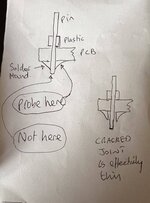
to rule out any cracked header pin solder joints - put probe to the side of the solder mound, not directly on the pin end
 
I know that there are lots of LED fans on here.

But Flash Gordon is 40 years old. It was never designed for LEDs.

Clean inserts, clean bulbs, clean bulb holders and properly working circuit boards produce beautiful effects in these Classic Bally SS games.

Leds like botoxing the Mona Lisa or siliconing the Venus de Milo
 
Okay. To be clear here, the problem is not with the LEDs.

The incandescents weren’t working either. It’s just I couldn’t see they weren’t working because they are based on a 100+ year-old technology that is barely visible in a well-lit room, uses loads of electricity unnecessarily and burns playfields.

Please, please, please only post here if you can help with the problem of getting two or three lights working, rather than commenting on whether you like LEDs or not. I personally think Flash Gordon looks much better when you can actually see the inserts.

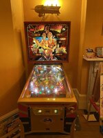
As the playfield has been hardtopped, the coin door, legs and side armour are gold powder coated, and it plays the Queen music very loudly, I think the LEDs are probably the least offensive thing about this pin to a early SS purist!! I’m really sorry about that, but the pin does look New-in-Box, as a result, and - as I was in nappies when this pin first came out - I don‘t have any nostalgia for it and I think its preservation is probably best achieved by its continued play which, in turn, is partly down to its to resemblance to a modern Stern!!0ADB99C4-833D-4859-99E9-FABE62DAB81F.jpeg
 
Last edited:
As a starter i would see what voltage the problem bulb holders get in the test mode - place meter on the wires where soldered to the bulb holders. Compare problem bulbs to working bulbs.

As above - are all these problem bulbs on the expander board? Or are they just rubbish bulb holders

These 40 yr old bulb holders are an absolute nightmare. Intermittent problems a gogo. You can mess about with them for ages. They give nothing but trouble. Hard core enthusiasts replace them all. You can buzz them with a dremel. Or remove and soak in evapo-rust. I do both these things.

If go faster stripes on an aston Martin are your thing, stripe away
 
Back
Top Bottom