What's new
Pinball info

Register a free account today to become a member! Once signed in, you'll be able to participate on this site by adding your own topics and posts, as well as connect with other members through your own private inbox!

Classic Bally/Stern flipper problem

Johnnyo

Not such a well known member.
10 Years
Joined
Jul 21, 2011
Messages
382
Location
Hertfordshire
Hi guys looking for some help with R/H flippers upper and lower on my Mr Mrs Pacman machine
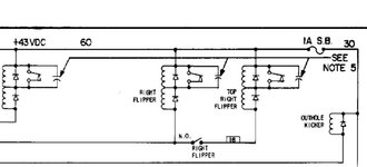
seem to have lost the power stroke to flippers but holding the flipper button in and raising the flippers
manually the hold winding is working, release button and flipper drops. Have checked all larger transistors
on solenoid board and all test ok.
Flipper coils have power so I am guessing something may have gone on the MPU board, looking on pin wiki and clays old guides the operation of the flippers is somewhat lacking in information.

Can anyone on here that can help me as to where to start looking would be greatly appreciated.

thanks in advance John
 
Hi John, I don't think the flippers are driven via a transistor, its much simpler.

43VDC to one end of the coils and the other end is grounded by the flipper cabinet buttons when pressed.
One gotcha in this is that the 'ground' wires from the buttons to the coils go via a series relay (flipper enable relay) with left and right contacts.

Basically, when the machine is ready, it powers the flipper enable relay so that pressing the flipper buttons will in turn power the flipper coils.

We know that this relay is at least energised otherwise the flippers wouldn't even hold when manually moved, but ... any high resistance at the relay contacts would prove too much for the high power flipper coil to function.
Exactly the same is true of the flipper cabinet button contacts, or indeed any high resistance in the entire path from ground to flipper coils.

So, check for grubby flipper cabinet button contact / flipper enable relay contact (sol. driver board) / ground wire to cabinet button.

good luck,
Rob
 
Last edited by a moderator:
On my old vector the flipper switches (behind buttons in cabinet) and the end of stroke switches (on flipper assemblies) were terribly pitted. These are high voltage switches and the only ones in the pinball designed to be filed down to clean them. The other switches (low voltage) are far more fragile and designed to be cleaned with a bit if cardboard.

I removed the switches, photographed them, dissembled them, and cleaned with thoroughly with dry, "wet and dry" paper to act as an abrasive. I wrapped my wet and dry on a chisel to make sure it was flat. I made sure that these were "square" when the contact was made too by bending the switches flat again

When I put them back together, the flipper performance was transformed.

Check at what point the end of stroke switches are triggered too. You can increase flipper power by setting the end of stroke switches correctly, so they are tripped just before the very end of the plunger's travel. Indeed on my vector I actually had to weaken the power of my left flipper by adjusting the EOS on this one, as the cleaned up switches made such a difference.
 
Another thing with these Bally games is that the upper flipper will be switched by contacts on the linkage of the lower one; you'll see two pairs of contacts on the lower flipper, its own EoS switch which opens to bring the coils' secondary winding into circuit, and another which closes to switch the upper flipper and repeat the process there. Quite often, only the button or lower flipper contacts are at fault when neither upper or lower work at all. The upper flipper can be checked by manually raising the main flipper paddle and pressing the button.

These flippers use 'series' coils, i.e. the two windings are in series. The Eos Switch shorts out the secondary winding while it's closed, so that the powerful primary winding pulls in the flipper solenoid plunger, then the combined resistance of both windings reduces the current flowing to a safe level once the EoS switch opens.

Like any solenoid, a simple test can be made by using a length of wire to complete the circuit to Ground. In the case of what I call a 'conventional' (i.e. not 'Solid State/Fliptronic') flipper, the primary winding can be checked by momentarily connecting a wire between the middle terminal of the flipper coil (the junction of the two windings) and the machines Earth/Ground, such as the braid inside the cabinet. If the winding's good, it should operate the solenoid. But only make the connection for a moment.

Correction: The above is suitable for Williams games - for a Bally game with series coils, ground the tail end of the coil (with the plain end of a diode attached) to by-pass the relay and button contacts.
 
Last edited:
Cheers guys will take another look and report back... no wonder I was scratching my head over this.

Sent from my U8666-1 using Tapatalk 2
 
Echoing comments from @DRD and @Jay Walker. The flipper circuit is independent of the MPU other than the FLIPPER RELAY on the REGULATOR/SOLENOID board. The relay allows the MPU to enable/disabled the flippers. The fact your flippers are still operational to some degree means you can rule out a problem there.

I would definitely look at switch contacts on the lower main flipper. In fact, just clean all of them on all flippers! A piece of card or fresh £20 note can be used. Just slip it in between the contacts and moved it back and forth until no more dirt. If the contacts are normally open then operate the flipper to close them up. You can use a proper contact cleaning file because these are high power contacts but don't be tempted to attack with a normal file or sandpaper, you'll just bugger them up. If they're really pitted and dirty then fit new ones.

I had exactly the same thing on my GOLD BALL when I first got it. The EOS (End Of Stroke) switch on the left flipper was so charred it wasn't making an electrical connection at all, but push the flipper up and hold the button and it would stay up.
 
You can't necessarily rule out the flipper enable relay. Yes it is energising but the r/h contact may be high resistance.

Also, for it to be the EOS switch contacts on the lower flipper, then both the NC and the NO would have to be bad. i.e. the bad NC would prevent the lower flipper operating, but if when John moved it by hand, like he said, the upper flipper should operate unless the NO contact was also bad. Still, stranger things have happened :)

Rob
 
Hi again guys
Well this has me stumped at the moment ... I have tried earthing the middle lug of the lower flipper coil as Jay says and nothing happens
have not long replaced the lower flippers EOS switch and secondary switch for upper flipper (both mounted on lower flipper)
could try swapping the coils around to see if it make any difference.

Movement of the connector plug wiring on the RH side of the solenoid board some times causes the relay on this board to flutter momentarily.

Other than that the flippers were working fine up until the other day when the R/H ones seemed to start losing power getting
weaker this was when they died completely.
 
Like any solenoid, a simple test can be made by using a length of wire to complete the circuit to Ground. In the case of what I call a 'conventional' (i.e. not 'Solid State/Fliptronic') flipper, the primary winding can be checked by momentarily connecting a wire between the middle terminal of the flipper coil (the junction of the two windings) and the machines Earth/Ground, such as the braid inside the cabinet. If the winding's good, it should operate the solenoid. But only make the connection for a moment.

no,no.
The 43V is directly connected to the 'hold winding' which is shorted out by the NC EOS switch.
if you short the junction of the two windings to ground you will likely kill the 43V ... short circuit through the EOS switch!
you need to ground the low voltage end of the 'power winding' to test it!

best check the LH flipper still works to make sure we haven't moved the goal posts. :)

Rob
 
Last edited by a moderator:
Sorry, I must've been thinking of the Williams series-coil wiring. The solenoid fuse on the power supply module could've blown, though maybe not if there wasn't a flash when the jumper was connected.
 
Last edited:
flipper schematic ..
 

Attachments

  • flipper.jpg
    flipper.jpg
    43 KB · Views: 12
Last edited by a moderator:
Ok S stands for stumped. But also stands for STUPID what a dickbrain I am,
When I was looking at why the RH flippers were weaker than usual I gapped both contacts on lower flipper as NO ::oops:
Thanks to all who gave advise very much appreciated this place rocks and with so many people who can help with superior knowledge of the darkside with early SS machines our community will live on regardless. Cheers John
 
Back
Top Bottom