What's new
Pinball info

Register a free account today to become a member! Once signed in, you'll be able to participate on this site by adding your own topics and posts, as well as connect with other members through your own private inbox!

Chicago Coin Playtime - Action Score Kicker

Dinkysaurs

Site Supporter
Joined
Oct 26, 2023
Messages
84
Location
Ipswich
I don’t suppose for one minute anyone on here has a Chicago Coin Playtime machine, but maybe they have worked on one at sometime

So, the problem…………

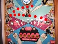
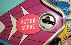
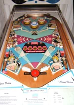
I had one of these in the 70s and when the ball went into one of the two “Action Score” cups (saucers) on either side of the playfield, it would kick it out, and if you were lucky it would do this back and forth between the two cups for maybe up to half a dozen times

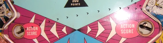
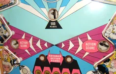
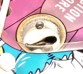
BUT, with this “new” one of mine, it either kicks the ball out too hard OR at the wrong angle, so the ball hits the rubber bumper above the cup – see my arrowed photo.

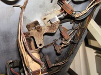
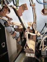
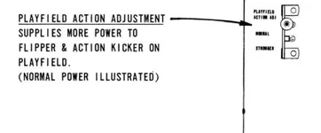
Now, going into the “works” there is a plug you can put into either a ‘Normal’ or ‘Stronger’ socket, and I thought Bingo! There is the answer – the plug is in the ‘Stronger’ socket, but no, it made no difference at all putting it into the Normal!

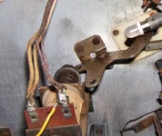
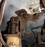
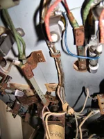
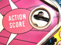
So, I thought well next, there has to be some sort of adjustment, but looking under the playfield at the underside of the cups/saucers they are rivetted to the underside of the playfield, and the cross-head screw inside the cups (see photos) seem to serve no purpose at all, as you can see quite clearly, they are screwed into the playfield board, not that you could get a screwdriver in there anyway!!!!

In conclusion, those two screws seem to serve no purpose whatsoever……………….

The only thing I can think of doing now, is to grab the actual kicker bar with two pairs of pliers and bend them to point in a slightly different direction, thus making the ball head more or less for the opposite cup and not the bumper.

Any help or ideas, would be most welcome, thank you
 

Attachments

  • ACTION SCORE 3.webp
    ACTION SCORE 3.webp
    90.3 KB · Views: 24
  • ACTION SCORE x 2 WITH ARROWS.webp
    ACTION SCORE x 2 WITH ARROWS.webp
    57.9 KB · Views: 25
  • ACTION SCORE x 2.webp
    ACTION SCORE x 2.webp
    124.8 KB · Views: 25
  • KICKER ADJUSTMENT.webp
    KICKER ADJUSTMENT.webp
    8.1 KB · Views: 29
  • PLAYFIELD.webp
    PLAYFIELD.webp
    109.5 KB · Views: 25
  • SCREW 2.webp
    SCREW 2.webp
    111.8 KB · Views: 23
  • SCREW.webp
    SCREW.webp
    117.5 KB · Views: 28
OK, so no one can help me with that, so have done some investigating, and what appears to me, with my limited knowledge, is that what has been used is a flipper solenoid, which is more powerful – hence the reason it is kicking the ball too high up the table and above the Action Score cups/saucers.

I had a brain wave and thought if I lowered the legs at the front of the machine, then gravity might counter balance the extra “hurl” up the table, but that didn’t work enough to cure the problem

The solenoids actioning the ball eject, look fairly new, well at least been replaced recently, which may well be too strong – the solenoids are FJ26-800, which means nothing to me (🎵Vienna🎶), so could someone help me with some technical advice, please

Thanking you in anticipation

John S
 
Hello,

Some coil numbering gives little idea of what the winding actually is, but in this case it seems to mean that there are 800 'turns' of 26 gauge wire. Decades ago, in electrical principles classes, the electro-magnetism module explained that the force produced by a solenoid winding depends on the product of the number of turns, and the current flowing in them. So, in theory more turns would produce more power. But in reality, the extra turns will increase the resistance and limit the current. So there's a balance to be struck on the number of turns. The other easily selectable factor is the wire thickness or gauge; the smaller the number the thicker the wire. A thicker wire can carry a higher current.

Btw, is it the FJ prefix which suggests it's a flipper solenoid?. A flipper coil usually has two separate windings, so the 26/800 would be the primary or Power winding. The secondary or Hold winding would be a lot more turns of thinner wire.

I've looked at ipdb for Chicago Coin games, with 1968 as the search term. There's a variant of Gun Smoke called Stage Coach, with a kick-out hole on the left, seemingly aimed at a free ball gate returning the ball to the shooter. The schematic lists the solenoid used for this and another kick-out as FJ 26-800. Whereas the flipper solenoids on this schematic are listed as FJ 21-375.

Your earlier idea of 'adjusting' the ejector arm(s) may have been the best method all along; some Bally solid-state games (Flash Gordon being one example) have a 'vector drawing' in the manual showing the intended pathway of a ball exiting an eject hole, with bending the ejector arm(s) as the method used.
 
Last edited:
Now that is all very interesting and I will read two or three times to digest it fully, so thank you so much for that.

From what I have read, the FJ suggested that was a code to identify the original manufacturer.

And what is the “ipdb” you mention?

And your “The schematic lists the solenoid used for this and another kick-out as FJ 26-800. The flippers on this listing are FJ 21-375” suggests FJ 26-800, is the correct one for a kick out, with the lesser powered (?) FJ 21-375 being for flippers, so now I’m even more confused, as clearly on my machine the FJ 26-800 solenoid is far too powerful

Very, very interesting the final piece about “adjusting” the arms (!), but I’ll leave that as a last desperate measure, if I cannot correct it electrically.

Can you add resistors on solenoids to cut down the power?

Thank you once again, for your most interesting post, and hopefully I’ll be able to post on here about how I resolved the issue……………….if I can, that is.😒

John S
 
Can you add resistors on solenoids to cut down the power?
Yes, but they need to be high current resistors.
e.g. :

If your coil measures say 10 ohms, then adding a 10 ohm resistor would approx 1/2 the power & similarly 5 ohm would approx 2/3 the power of the coil etc.
 
Yes, but they need to be high current resistors.
e.g. :

If your coil measures say 10 ohms, then adding a 10 ohm resistor would approx 1/2 the power & similarly 5 ohm would approx 2/3 the power of the coil etc.
Thank you, I'll have to get my meter out 😁
 
Might I suggest that the machine you played in the 70's wasn't supposed to behave like that and that the one you have now is correctly operating (so no adjustment needed)...!
 
  • Like
Reactions: HHH
Might I suggest that the machine you played in the 70's wasn't supposed to behave like that and that the one you have now is correctly operating (so no adjustment needed)...!
I don't think so. The point of the "Action Score" kickers is that they would give you an added bonus of up to 6 times back and forth, whereas my present one just hoofs the ball above the opposite kicker, which is totally pointless, but nonetheless, thank you for your suggestion 😊
 
The Ipdb is a yankee-hosted website, the International Pinball Data Base, 'ipdb dot org'. Using its search function with Chicago Coin as the manufacturer and 1968 as the year brought up listings for Playtime and Gun Smoke, a couple of rifle shooting games, and the 4-player version of Gun Smoke, this Stage Coach. The latter is the only one with a schematic in the attached links. This lists the coils and relays used, and the kick-out holes are listed with 26-800 coils.

While consulting the schematic for a different game isn't ideal, it can give an idea of what the manufacturer was using at the time. St/Coach, as with Gun Smoke, has a kick-out over on the left side, with a lifting 'Free Ball' gate placed across from it. This may be a similar case to Playtime, with the kick-out intended to send the ball through the open gate and back to the shooter.

Sorry to confuse the issue by mentioning the flipper coils listed in the SC schematic. 21-375 would be more powerful than 26-800. 21 gauge is thicker wire than 26, and the lower number of turns would have less resistance. That's the primary winding, the C/Coin part number gives no details of the secondary/Hold winding. Hold on, though, the SC schematic shows a separate 'Resistance' for each flipper coil. Well, well. But it's drawn as a winding, and another different schematic (of the previous year's "Beatniks") offers the value 28-400 for the secondary resistance winding to go with 21-375.

As to the designers' intention re. the 'Action Score', the only user rating attached to the ipdb entries for PT mentions that they did pass the ball back and forth on the example the respondent played - "the highlight of your game".
 
Last edited:
Thank you so much Jay, as that is all very, very interesting! Even if some of it contradicts what I’ve found out and was thinking in my non-technical mind 😉😁

Yes, the Gunsmoke machine, which I had for a short while, does have the same kicker on the left hand side, which hoofs the ball across the table, to hopefully an open gate to the plunger to continue playing with the same ball – the Playtime is the same idea, but not a gate on the right, but another kicker to send the ball, hopefully, back and forth across the table, racking up extra score – as you have noted from the ipdb - "the highlight of your game", which it was, in the 1970s!

NOW, on the Playtime I had in the 70s, this is what the machine did, but this exact same refurbished model I now possess, kicks the ball out too hard across the table to above the opposite kicker and so the back and forth does not happen, which is clearly a pointless exercise.

So, there was me thinking the higher the number of turns on the coil, indicates a more powerful solenoid, which clearly I have got wrong from what you have said, and that the 28-800 solenoid on the kickers in my “new” machine appear to be the correct ones, which I now find totally confusing – leaving me back at square one.

So, why is it kicking the ball too high up the table, above the other kicker? I’ve studied the physical details of the kicker underside, and it is original and rivetted with no adjustments. I did have one brain-wave and that was to lower the front legs, letting gravity sort it out, but it did not make one ounce of difference, so see no point in raising the back legs.

I really don’t know where I go from here, apart from physically altering the kicker by bending it, as you said previous – “Your earlier idea of 'adjusting the ejector arm(s) may have been the best method all along; some Bally solid-state games (Flash Gordon being one example) have a 'vector drawing' in the manual showing the intended pathway of a ball exiting an eject hole, with bending the ejector arm(s) as the method used.”, which gives some hope, but sounds a bit drastic!

I attach a photo of the play area, showing the path the ball should travel, with a red ball showing what is actually happening.

Thanking you once again

John S aka Dinkysaurs
 

Attachments

  • TABLE 3.webp
    TABLE 3.webp
    153.2 KB · Views: 9
Can you take a photo of the underside?

I'm wondering if 50 years of wear means you need new end stops for the kicker... worn out end stops might be affecting the strength of the kick out..?
 
Thank you, though not quite sure what you are referring to with "end stops", but will certainly take a photo of the underside, as it sounds as though that might be the cure 😊

You'll need to give me a day or two, as I need a hand to slide the glass out - I used to do this on the old one, but don't trust myself to do it on my own now.
The solenoid which operates the kicker will have an end stop (coil stop) of some kind, I can’t immediately find the part number for Chicago Coin but it’ll be on the end of the coil opposite to where the plunger goes in and out.

Worn coil stops can make mechs behave oddly. You won’t be able to see the level of wear without removing the stop from the machine, as it’ll be sitting inside the coil.
Thank you, but gulp, I'll see what I can do, as I'm not that au fait with taking things "to bits" 😟
 
If you don’t want to disassemble anything then your only option is to try to bend the kicker arm and/or adjust the pitch of the machine even more to try to get it where you want it

If you do disassemble stuff, just take lots of photos (more than you think you need) so you’re always working towards a picture, then you can’t go too far wrong
 
I'm only asking for a photo from under the playfield at this time to see what they look like. Some games just have a piece of metal there and it's possible to adjust by just bending the metal slightly. I don't think that's the case here but it's worth a look with a photo or two to see if there's anything obvious or if there's an equivalent mechanism from another game.... You keep mentioning that it's rivetted, I've no idea where or how without a photo. For all I know you could be describing the end stop, as that can look like they're rivetted. If that is loose (as an example) then that could be the cause of your problem but without a photo it's hard to advise.
 
If you don’t want to disassemble anything then your only option is to try to bend the kicker arm and/or adjust the pitch of the machine even more to try to get it where you want it

If you do disassemble stuff, just take lots of photos (more than you think you need) so you’re always working towards a picture, then you can’t go too far wrong
Thank you, that's a priority for today, as my son is coming round to give me a hand. As I mentioned before, I have dropped the front legs down to max (or is that min. 😟) but it has made no difference whatsoever, and so am loath to raise the back legs, as I wonder also how much that will affect the speed of the balls descent
 
I'm only asking for a photo from under the playfield at this time to see what they look like. Some games just have a piece of metal there and it's possible to adjust by just bending the metal slightly. I don't think that's the case here but it's worth a look with a photo or two to see if there's anything obvious or if there's an equivalent mechanism from another game.... You keep mentioning that it's rivetted, I've no idea where or how without a photo. For all I know you could be describing the end stop, as that can look like they're rivetted. If that is loose (as an example) then that could be the cause of your problem but without a photo it's hard to advise.
Yes, thank you. Some photos today, and had considered the bending of something, but as that sounds a bit drastic, I'm clutching at straws to see if there is a "proper" way.
 
UNDERSIDE PLAYFIELD KICKER SOLENOIDS - Chicago Coin Playtime machine

OK, so I hope these are er, OK as it is the best I can come up with, without dismantling anything, and hope someone can let me know, anything, thank you 😊 If you do need more detail, then I will have to bite the bullet and get me screwdrivers out 😟
 

Attachments

  • DSCF5304.webp
    DSCF5304.webp
    160.6 KB · Views: 10
  • DSCF5305.webp
    DSCF5305.webp
    166 KB · Views: 9
  • DSCF5306.webp
    DSCF5306.webp
    138.1 KB · Views: 7
  • DSCF5309.webp
    DSCF5309.webp
    92.6 KB · Views: 6
  • DSCF5311.webp
    DSCF5311.webp
    88.5 KB · Views: 8
Back
Top Bottom