What's new
Pinball info

Register a free account today to become a member! Once signed in, you'll be able to participate on this site by adding your own topics and posts, as well as connect with other members through your own private inbox!

CFTBL - Strange Issue - Challenge

Calimori

Staff member
Joined
Mar 15, 2012
Messages
4,525
Location
Bedfordshure, UK
I fixed this issue already but I wanted to turn the experience into a learning exercise and see if there is a better way of diagnosing these sorts of issue.
It was also an odd one, with the initial 2 symptoms appearing unconnected.
My solution had me checking for the wiring of the issue areas and looking at the manual and schematics to work out what to test before landing on the one part most likely to have failed.

I want to hear what others would have done to troubleshoot and narrow it down, consider it a challenge or puzzle. But there are no points if there you don't show your workings or logic and no guess work.

The starting information:
  1. Machine is CFTBL
  2. Issue presented as:
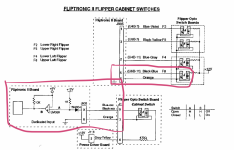
    1. Left flipper fully pressed powered two flashers on the backbox on the orange-grey wire
    2. Switch error for F8, upper left flipper upper, black-blue

I only used the following documents:

Questions:
What board needed repair?
What component?
How did that failure cause the two separate symptoms?
 
Left flipper fully pressed meaning second opto for upper flipper activated?
If so, Fliptronic II as these flashers are controlled via it. Probably U2 or U5 as D7 is pulled high by activating the switch enabling the flasher.
 
Last edited:
Left flipper fully pressed meaning second opto for upper flipper activated?
If so, Fliptronic II as these flashers are controlled via it. Probably U2 or U5 as D7 is pulled high by activating the switch enabling the flasher.
Yes to the first question, F8.
Edited: You have highlighted that this is on the Fliptronic board and that both the switch and the flashers are connected.
No, it wasn't U2, U5 or D7.

Screenshot 2023-09-15 at 10.18.04.png

League Table

NamesPointsReason
@Paul 1Identified board
@drhex1Identified board
 
Last edited:
So something driving D7 high on the CPU write cycle if the button is pressed. Only happening for one channel if this is the complete fault description, should therefore not be output inhibit on U5 as that would affect the other switches, too. This is where I would start to measure on the board.
 
Last edited:
OK, if that is indeed what was happening I can only see 74HCT244 U5 as the problem, there is no reverse path being opened by the switch as far as I can see. Again, easy to figure out if you have the board in front of you.
 
As per my first line, I have fixed it already. It wasn't U5 that I replaced. I think this has run it course so I will say what I did and experienced folks can tell me how I could have done it better.

  • I swapped out the board for a known good one, proving it was on the board.
  • I then walked through the diode and resistors and was able to be fairly confident they were fine.
  • LM339 at U6 seemed like the obvious answer so I replaced that and fixed the issue
    • I was able to test that the chip had failed.
 
Interesting, I excluded U6 in my mind as U5 is essentially the gate keeper for the signals generated there - U6 just compares the switch signal to VCC and generates an input for U5. U5 is then putting the input level to the data lines when the CPU requests this. For the problem you've been seeing it must pass the high state of the input to the D7 data line when the chip isn't selected, i.e. the CPU intends to set the levels to control the flippers or flashers. Can see how a broken U6 would keep the switch stuck on but not how it would cause this behavior. Anyway, it works so all good.
 
Thanks for sharing that as it is this level of detail that I have not yet been exposed to. Interesting to hear that it wasn't obvious that failure of U6 would cause the errors.
My thought was what would cause the CPU to not see the switch being closed but was still triggering a response when the switch was closed. U6 was the first in the line, U5 was next.
 
Indeed, if you look at the schematic, you will see that U5 pin 1 and 19 are driven by the CPU via CS and R/W signals. This is done to put the outputs of U5 into tri state when the CPU wants to activate outputs. Similarly, U2 takes in data from the bus when the clock transistions and it is enabled on pin 1. So U5 should never have data on the bus when U2 activates outputs or you'll see the effects you described as the CPU data will be overlaid with whatever is on U5's inputs. Now U6 is just conditioning the switch signals for U5, so replacing it must have jogged something in U5 getting it to work again.
 
all this stuff is gobbledegook to me.
Would love to know about this stuff, same when lot go on about writing code etc..

Haven’t got a scooby doo what is going on! giphy.gif
 
@drhex is certainly on another level to my troubleshooting. I will spend some time trying to walk through the circuit and see what he is saying.

One thought, theU6 did also test as being failed. Could it have be polluting the signal on D7? I currently don’t have a bench test set up but hoping it arrives soon. Then I could use a probe on it and watch it running
 
Yes, could be. But: pressing the button did something, so the signal must have traversed U6. Would have been interesting to put a scope on the board when it didn’t work.
 
Back
Top Bottom