Register a free account today to become a member! Once signed in, you'll be able to participate on this site by adding your own topics and posts, as well as connect with other members through your own private inbox!
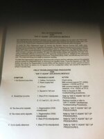
Is the set up procedure in the original bally manual for centaurs say it again board mis-printed?,it says connect tp3 and tp4 together,but there is nothing marked tp3 on the board,that I can see?
after replacing a crappy bit of bodged wiring from the s+t to the SIA,I have sound and reverb,I was just trying to follow the set up procedure as per the manual,still I suppose I should leave it alone,whilst it's working
I set (or rather re-set) one many years ago, and all the test points mentioned are on the reverb board. According to schematics on ipdb, TP3 is for "Test Oscillator"*, and connecting to TP4 links this to 'Audio In'. The actual point is shown as the junction of Resistors 62 & 63, which connect between U1, pin 10 and Ground (R62 to the chip, R63 to ground). But as you've recovered the reverb, I'd leave things be.
* Seemingly provided just to set the bias for reverb; it's only enabled by linking TP1 to TP2.