kamalackarie
Site Supporter
sorry TP3 only showing 8vdc
yes it is - veryIs the new voltage regulator getting hot?
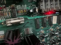
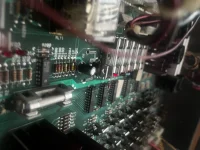
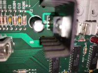
Thank you for that. i had the heatsink out just while i am testing - its back in now.There are traces topside. And q2 needs a heat sink.
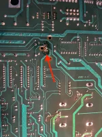
I get nothing between the output on q2 and c2. I do get continuity between the ground on q2 and ground on c2. I assume they share a common earth.Yes and one end of c2.
I get nothing between the output on q2 and c2. I do get continuity between the ground on q2 and ground on c2. I assume they share a common earth.
I went ahead and tested continuity between the cap and F115. No problem here. I have continuity
At this stage I think I need to replace c2 and see what happens. It seems it’s either a faulty cap or the trace between it and q2 output.
I’ve ordered a replacement and will get back to this on Monday as I’m away this weekend.
Thank you for your help
Do you have continuity between output of q2 and f115? If you don't the trace is broken and you will need to reinstate. Easiest way is a jumper wire between the 2 but do ensure you get the correct end of f115 to jumper to otherwise you could bypass the fuse.I get nothing between the output on q2 and c2. I do get continuity between the ground on q2 and ground on c2. I assume they share a common earth.
I went ahead and tested continuity between the cap and F115. No problem here. I have continuity
At this stage I think I need to replace c2 and see what happens. It seems it’s either a faulty cap or the trace between it and q2 output.
I’ve ordered a replacement and will get back to this on Monday as I’m away this weekend.
Thank you for your help
Good morning.Do you have continuity between output of q2 and f115? If you don't the trace is broken and you will need to reinstate. Easiest way is a jumper wire between the 2 but do ensure you get the correct end of f115 to jumper to otherwise you could bypass the fuse.

 www.aussiearcade.com
Before you go to all that pain - have you tried reseating the Asic?so it seems the issue is with the ASIC which needs replacing - makes sense as the machine was shorted