What's new
Pinball info

Register a free account today to become a member! Once signed in, you'll be able to participate on this site by adding your own topics and posts, as well as connect with other members through your own private inbox!

Bride of Pinbot LED & Mylar problem?

Martin.D

Registered
Joined
Jul 28, 2019
Messages
144
Location
Bromley, Kent.
Alias
No-Clu
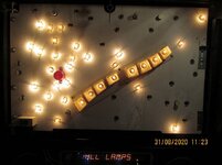
Updating and servicing new purchase, found odd problem with backbox lighting:

Outter track LED White/Green & Green wires not working.
4 LED Pinbot faces under DMD no power.

Tracked to J121 pins checked White/Green & green pair show 4.5, Brown & Grey & Grey pair 6.3 & Yellow & White & Yellow pair show nothing.
Suggested cause and possible solutions? Was maybe thinking running of power from somewhere else if needed.
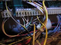
J121.JPG

BackboxLiights.JPG

Also would be interested to hear comments on removing playfield mylar? Good/bad and HOW safe?
 
Last edited:
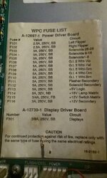
Fuse
Or bad connection on j115 or cracked or bad pin on j120 or j121

Checked all fuse with multimeter and visual checked to see fuse not blown.
Removed and replaced related fused as listed in machine.

FuseList.jpg

J121 pins and socket not loose and solder on back of board does not look damage.
Reading from J121 seem to change maybe another related component?

Proposed action moving effected wires to another pin, but manual does not list pinouts of power driver board. Is there one?
It is possible to combine Brown/ Grey & Grey pair (Body lights of pinbot on backbox) + White/Green & green pair (Outside edge lights backbox)?

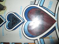
As for Mylar cracked and bubbles. Wonder how hard to replace or remove?

Mylar.JPG
 
Morning @NoCLU

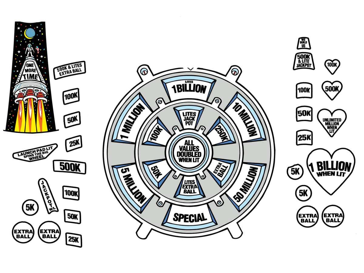
You can always fit an overlay....

Do not go for the complete playfield overlay by the way - these insert ones are better. I would carefully score around the instert and remove the old one and stick on the above!

You are bring pointed the right way with the other comments. Next job - check the soldering of the pins on that - and the fuse holder (have you checked all the GI fuses). Next check the GI connection on the main board from the transformer. It is on the bottom left hand side of the Power driver board. Also check the molex on the transformer (but can not see it being that).

Check all fuses out of the board with a multimeter. Not by sight or on the board.
 
If everything is ok on the connector s then look at the connector in the cab by the transformer may be burned
Yes you can join the wire together but this is a bodge not a fix
You will do more damage than good trying to remove the Mylar
 
Removed Re-tested fuses all seem fine, but ordered some replacements anyway.

Coming back to my original test above " J121 pins checked White/Green & green pair show 4.5v, Brown/Grey & Grey pair 6.3v & Yellow/White & Yellow pair show nothing. ".
There seem only 2 PCB tracks going into this socket which I assume means only 6v+ and ground? So by logic all pins should pins should be 6v+ OR ground. With this in mind should be bad joint/cold solder problem? Even though board shows no sign.
Man this would be easier if manual provided all pin outs for power board.

Does anyone service boards on there own? Without having to ship whole machine.

Will check transformer anyway. Looking into everthing as I clear machine.
 
There seem only 2 PCB tracks going into this socket which I assume means only 6v+ and ground? So by logic all pins should pins should be 6v+ OR ground.
Note that the GI is AC voltage, so are you measuring across the two wires with your meter set to AC?
 
Note that the GI is AC voltage, so are you measuring across the two wires with your meter set to AC?
Yes measuring pairs in AC voltage. But my point remains the same all pins on socket J121 same?
 
Last edited:
Connector in the cab by the transformer and voltage are both ok.

Ok much testing here is backbox G.I. plug (11 pin) which can be plugs into socket J120 or J121:
AC tested in pairs (X is end pair and reading in AC):
0.63000.020.687.252.45KEYX
5.556.466.166.145.501.06KEYX

KEYX6.12
KEYX6.12
KEY6.12X0.03

2.001.882.151.882.150.18XKEY
6.587.207.207.206.55X0.18KEY
0.040.640.640.64X6.540.18KEY
0.680.030.03x0.647.182.56KEY
0.680.03X0.030.647.182.56KEY
0.68x0.030.030.037.182.56KEY
X0.600.600.580.036.632.12KEY

Now have working outter track LED White/Green & Green wires on backbox and 4 LED Pinbot faces under DMD. By just moving wire.
But would like to hear if anything jumps out as odd from tabled reading?

Assuming someone can spot a problem from information. Thinking maybe bad PCB component on one of the left tracks?
 
Last edited:
Checked all fuse with multimeter and visual checked to see fuse not blown.
Removed and replaced related fused as listed in machine.

View attachment 118287

J121 pins and socket not loose and solder on back of board does not look damage.
Reading from J121 seem to change maybe another related component?

Proposed action moving effected wires to another pin, but manual does not list pinouts of power driver board. Is there one?
It is possible to combine Brown/ Grey & Grey pair (Body lights of pinbot on backbox) + White/Green & green pair (Outside edge lights backbox)?

As for Mylar cracked and bubbles. Wonder how hard to replace or remove?

View attachment 118289


bop Mylar comes off fairly easily with freeze spray but it leaves a lot of glue which is harder to get off without softening or taking off the existing clear coat .
 
If everything is ok on the connector s then look at the connector in the cab by the transformer may be burned
Yes you can join the wire together but this is a bodge not a fix

Ok think I have traced power fault. J115 connector rust and bad connection inside, not easy to spot outside. Replaced header connector and all G.I's now working.
Can anyone just confirm wires in original picture (Which starts this post) of J121 are in correct place? My picture is how wires connected when I original got table. Plan to put wires back into original locations on connector.

Interested to know cause? so not to repeat.
 
Did I not tell you it would be a connector in august 😂
Do you have a manual the wireing for the connector s will be in there if you don’t have the manual I can look for you tomorrow
It’s common for these to burn out with them using ac and been on for long periods of time with heavy current drawing bulbs ones changed you shouldn’t have a problem again particularly if you are using leds
 
Yep bitch to find, connector had no decolourisation. Found as blow fuse checking underside playfield lighting sockets (Which should not happen). Also 2 fuses wrong amp size, which might contributed to problem.
BTW I hate these connectors, pain to get wire in without correct tool (Which I now have).

Yes have manual will check again for wire setup for this connector. but did not see manual show which wires on which pins. Checked my picture with others on Internet and seems to match but better safe than sorry.
 
Back
Top Bottom