What's new
Pinball info

Register a free account today to become a member! Once signed in, you'll be able to participate on this site by adding your own topics and posts, as well as connect with other members through your own private inbox!

BK3 flaming speaker lights (was: Trying to understand speaker light kits)

Fubar

Site Supporter
Joined
Feb 5, 2020
Messages
1,716
Location
Cambridge, UK
Alias
Thomas
So I'd like to add the flaming speakers mod to my BK3. Some info on this pinside thread: https://pinside.com/pinball/forum/topic/bksor-flaming-speaker-mod-diy


I'm happy to source the arduino and LED strip myself, do soldering, etc.

What I'm trying to understand is:
  • What mounting hardware do I need - is it just a matter of adding an acrylic frame around the opening and using longer screws, or is there something more? Where can I source said frame?
  • Do I really need a separate AC->DC power supply or can I just tap into one of the game's DC rails? Ideally 5V so I don't need a step-down regulator, but if that's not adequate I'm sure the 48V rail has plenty of juice...
Thanks in advance :)
 
  • What mounting hardware do I need - is it just a matter of adding an acrylic frame around the opening and using longer screws, or is there something more? Where can I source said frame?
  • Do I really need a separate AC->DC power supply or can I just tap into one of the game's DC rails? Ideally 5V so I don't need a step-down regulator, but if that's not adequate I'm sure the 48V rail has plenty of juice...
Bump - anyone? :)
 
Not exactly the same - tricky as my lights are smaller and round... but inspired by your find - this is how Feed Frenzy Speaker lights look with software configured Fiery Furnace
 
So I'd like to add the flaming speakers mod to my BK3. Some info on this pinside thread: https://pinside.com/pinball/forum/topic/bksor-flaming-speaker-mod-diy


I'm happy to source the arduino and LED strip myself, do soldering, etc.

What I'm trying to understand is:
  • What mounting hardware do I need - is it just a matter of adding an acrylic frame around the opening and using longer screws, or is there something more? Where can I source said frame?
  • Do I really need a separate AC->DC power supply or can I just tap into one of the game's DC rails? Ideally 5V so I don't need a step-down regulator, but if that's not adequate I'm sure the 48V rail has plenty of juice...
Thanks in advance :)
The frames, mounting hardware, power transformer and much of the needed parts for this mod are included in my Type 12 SPIKE 2 Speaker Light Kits. I believe that is explained on the pinside thread that you linked to.

Doug (SpeakerLightKits.com)
 
I wouldn't be tapping into the power supply in your machine to add ANYTHING! That is inviting trouble IMO.

Keeping this, and other mods, running from a separate power source is the ONLY way to go.

The engineers that designed the electronics in your machine DID NOT allow for additional loads no matter how small you might think these loads are.

This is the reason Homepin provides a 100% separate, 12V 3A power source in our machines so people can easily add mods without butchering the original wiring and overloading the design of the power supply.
 
Thanks for all the advice guys :)

@DugFreez the reason I'm investigating alternatives is to avoid getting superfluous items. If you're willing to supply a partial kit then I'm happy to order from you or via pinball bazaar :thumbs:
 
Thanks for all the advice guys :)

@DugFreez the reason I'm investigating alternatives is to avoid getting superfluous items. If you're willing to supply a partial kit then I'm happy to order from you or via pinball bazaar :thumbs:
If you buy my Type 12 light kit...you would use everything except the light strips themselves (though you would be using the connector ends and magnets from them) and the RGB controller and remote (though you would be using both of the ends of the RGB controller).

So very little is NOT used from my type 12 kit. If you would like to order a Type 12 kit from me without the light strips and RGB controller and remote....it would be $10 off.

Doug (SpeakerLightKits.com)
 
If you are grabbing power from the game grab it from the power board next to the PSU or from the coin door a or not at all IMO - Stern games super flakey with power - Doug’s solution is a good one which is to split the AC power into a dedicated DC convertor.


Sent from my iPhone using Tapatalk Pro
 
The AC power at the bill acceptor is a good place to pull the power for your stepdown transformer. Its generally the Black and White thicker wires near the coindoor. Most PSUs are 110-240V so this will be fine.
As for the Flame effect this would be done easily using Mikes Feed Frenzy like someone said above just use 2 strips either side in parallel and I know mikes has a similar effect in the app and if not happy you can create your own.
If yours is the Prem/LE BKSOR then just remove the foam and fit the strips around the edge but if its the Pro you would require Dougs speaker bracket and you could upgrade your speakers at the same time.

Looks to be worth the effort so good luck with your project.
 
If yours is the Prem/LE BKSOR then just remove the foam and fit the strips around the edge but if its the Pro you would require Dougs speaker bracket and you could upgrade your speakers at the same time.
I don't think that's as easy as you think it is. "just remove the foam and fit the strips around the edge"? The edge of what? The inner speaker panel? I'm not sure you understand how the SPIKE 2 speaker panels are made and how the LCD screen and speaker plates mount on them or I may be misunderstanding what you are suggesting. Without moving the speaker plates back....how are you going to see any light from between the front of the speaker plates and the back of the honeycomb grill on the panel if you just "fit the strips around the edge"? If you just move the speaker plate back with spacers.....what's going to hold the LCD screen in place?

Just throwing some lights in there isn't as easy as many would think. It took a lot of thought and work to get my light frames designed and looking as good as possible. I know many were trying to do it using different types of materials. As of now....the copies to light the entire grill area are just starting to trickle out. Most of the copying folks just gave up and continued to use the small 4" light frames behind the speaker holes in SPIKE 2 games, because continuing to use a copy of my old light frame design was easier than trying to copy my new frames or, heaven forbid, come up with a new idea of their own. I'm sure most of the upcoming "fully lit grill" copies will be using 3D printed materials, acrylic or some other substitute that is easier for the seller to make. They can make one offs as needed and have no risk. I mean why buy a minimum order quantity of 400 pcs of an aluminum frame that will help to dissipate the heat from the light strips and lengthen their life when you can cut 14 pieces of acrylic to glue together to make a "light frame" to stick light strips in? ....but I guess I am getting a bit off topic here.

I'm also not seeing any difference if a person has a premium, pro or LE and using either the 4" or 5.25" speaker plates for this type of project. The only real difference in them is the the size, look and location of the speaker holes in them. I don't see how that has anything to do with this type of project except for a visual difference IF a person isn't using the speaker foam.

Speaking of which, I also think a person would want to leave the foam in (or buy foam if their game didn't come with it) for this project. I've never seen a side by side of the flaming frames with and without foam, but I'm expecting the foam left in to diffuse and spread the light from the strips would help with the look. I'm also not sure what the clear plastic canvas that people sometimes put behind the foam would do for the look of things on this project. My friend did this flaming frames project on his BK:SoR. He left the foam in and added the clear plastic canvas behind the foam. It looks great, but as I said, I didn't see it without the clear plastic canvas or foam to see how that looked in comparison.

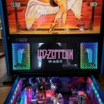
If a person did do the project and decided to leave the foam out.....I would recommend trying some black plastic canvas (available at most craft stores) IN THE BACK of the lit area (behind the light frames and just in front of the speaker plates). Especially if they are using the ugly 4" speaker plates. This should cover up the view of the off center, 4" speaker holes with the bars running through them. The texture of the plastic canvas might also add a cool look to the flaming pattern....but then again...it might be a bit of a visual distraction and clutter up the flame effect. I think it would be worth a try though. My friend did this on their Led Zeppelin LE to cover up their speakers in the back of the fully lit speaker grill area and it worked out quite well. SEE ATTACHMENT
 

Attachments

  • LZ T12 01.JPG
    LZ T12 01.JPG
    163.4 KB · Views: 28
Wow looks like I’m being schooled. Again!
Was just trying to help as usual but apologies if I’m wrong I’ll keep out of the thread.
Anyway having family some family time and that’s a bit long for me to read through ATM so will check back later and read but not reply.
 
The LE doesn’t have any foam either?


Sent from my iPhone using Tapatalk Pro
 
The LE doesn’t have any foam either?


Sent from my iPhone using Tapatalk Pro
I Should have known that Neil as I have had several LEs myself So stand corrected.

I said I wouldn’t reply but after a few PMs of support from the community I will.

The whole point of the thread was someone asking for help in making his own speaker lights as a project for himself (which I tried) but kinda went into bashing and belittling everyone who has a go me included With my 14 piece acrylic ones which BTW don’t overheat and lessen the life of the £5 LED strip at all IMO!

Actually one of my LE‘s came with an expensive set of speaker lights where the LED strip was sandwiched in between a 3D printed speaker bracket which I would have thought would produce a hell of a lot more heat than my open design but hey what do I know mabye plastic is better than acrylic for this application but either way I digress.

Bear in mind Neil not everyone in this hobby has copious amounts of money and a cheap DIY alternative will always be welcome, especially when other members in the community like MadNat ask me to produce something like he has for his amazing feed frenzy board. I will always happily help where I can.

I do not want to derail this thread any further and prefer if we just got back on track so if I can be of any help to anyone just pm me and I’ll try my best.
 
Big fan of Cols work. Great member of our community - very helpful fella, can’t imagine anyone would disagree.

Doug clearly has some great experience also - I see you recognised you got off topic… fair play for that. Clearly there are many ways to deliver similar outcomes - anyone attempting a similar outcome is definitely not a copy. My opinion - bit too strong to suggest that.

By the way - who invented the first pinball machine - I don’t think all those who followed were copies (first part is a genuine question btw!).

Anyway - this is a forum, where ideas, suggestion, comments are free for all to share… ideally not fuelled on ale, wine and/or spirits - sometimes gets messy when you throw those into the mix! [emoji23]
 
I posted on this thread to help also. Additionally, I have been in contact with the guy that wrote the pinside DIY tutorial on this type of flaming speaker project as well as the guy that originally did this type of mod and with Fubar and others about it via private message and e-mail.

No offense intended by questioning others suggestions, but I didn't see how saying take out the foam and throw some lights in it was helpful. As that just doesn't make any sense with the SPIKE 2 speaker panels. Never have I got on any of the flaming speaker light threads and tried to dissuade anyone from making them or accused them of copying anything I have done (as they have all used my SPIKE 2 light frames as far as I know). One of the folks on the pinside thread...I sent extra connectors and various other things for his DIY flaming project along with his type 12 light kit.

I didn't say anything about any other light frames causing the LED light strips to overheat. I was just pointing out that aluminum, which I use for my 4" light frames (the SPIKE 2 fully lit frames are steel), is commonly used for LED light strip channels as they have the added benefit of displacing the small amount of heat that the LED light strips do put off. Just because one is better than the other doesn't mean I was accusing the other of causing issues with the light strips.

In any case, on the pinside thread linked to on the origional post, I listed what my type 12 light kit does and does not include if one wants to try this type of DIY SPIKE 2 flaming speaker mod and wants to get most of the needed parts from one place. I'm expecting there are other ways to get the light strips in there, but I'm also sure "just removing the foam and fit the strips around the edge" isn't going to be good enough. You are going to need a frame / bracket of some sort to hold the light strips, as well as securing the LCD screen to the panel.
 
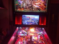
Finally got this wrapped up last night - looks ace!

Changed it slightly so that I could run a single strip in a 'U' shape, rather than two Ls with hacked-up wiring as described in the original pinside thread. This required some minor surgery to the arduino code which I can share this evening...

IMG_20210602_231541.jpg
 

Attachments

  • IMG_20210603_105240.jpg
    IMG_20210603_105240.jpg
    136.3 KB · Views: 28
Finally got this wrapped up last night - looks ace!

Changed it slightly so that I could run a single strip in a 'U' shape, rather than two Ls with hacked-up wiring as described in the original pinside thread. This required some minor surgery to the arduino code which I can share this evening...

View attachment 139579
Nice and it looks like you managed after all with the factory plates well done.
 
I did get one of Doug's kits from Pinball Bazaar. The steel frames from that kit are the bit that's tricky to DIY. And getting the other bits like the PSU, hex spacers, and connectors / Y-harness all in a single package was definitely convenient (and probably not more expensive than paying N shipping fees to various suppliers).

I tore out the kit's LED strips (which only had magnets for a short length, then were glued - sounds like the factory trying to save money *sigh*), and discarded the provided LED controller and remote.

The reason for changing the LED strips in the speaker light kit is to use ones with higher LED density (144/m), as otherwise the flame effect looks a bit naff. If you could get a speaker light kit with these 144/m LED strips, that part of the build wouldn't be required (do it, Doug! ;)). I used 2 of these (they're 1m and unfortunately you need 56cm/speaker...): https://www.amazon.co.uk/dp/B07TB198W5 (YUNBO WS2812B Individually Addressable RGB LED Pixel Strip Lights, 144LEDs 3.2FT/1M Black PCB Flexible IP20 NO-Waterproof Cuttable 5050 SMD IC 5V Smart LED Lighting).

There's still one open issue I need to tackle, and that is the fact that I couldn't fit the hex spacers in the bottom of the left speaker - the LED strip gets in the way, I guess the one I used is thicker than the kit's stock one... I also don't love the fact that the locknuts don't tighten all the way on the plastic hex spacers (unless I overtorque the whole thing, which I'm not going to), although I don't see it causing any issues in practice. Trying to undo the locknuts also doesn't achieve the desired outcome (the hex spacer unscrews from the base instead). Just one more evening of faffing around - that's why we've got pinball machines, right?! 😁
 
Here's a video :)

And the code I used (from the pinside thread linked in OP). I made some change to support addressing the strip from one end instead of the middle as originally.

Updated 4.06.2021 -- fixed the 4 simulations sharing the same heat array when they shouldn't.
C:
#include <FastLED.h>

// D2..D5
#define LED_PIN0   4
#define LED_PIN1   5

#define COLOR_ORDER GRB
#define CHIPSET     WS2811
#define NUM_LEDS    39

#define BRIGHTNESS  200
#define FRAMES_PER_SECOND 40

CRGB leds[4][NUM_LEDS];

// Fire2012 with programmable Color Palette
//
// This code is the same fire simulation as the original "Fire2012",
// but each heat cell's temperature is translated to color through a FastLED
// programmable color palette, instead of through the "HeatColor(...)" function.
//
// Four different static color palettes are provided here, plus one dynamic one.
// 
// The three static ones are: 
//   1. the FastLED built-in HeatColors_p -- this is the default, and it looks
//      pretty much exactly like the original Fire2012.
//
//  To use any of the other palettes below, just "uncomment" the corresponding code.
//
//   2. a gradient from black to red to yellow to white, which is
//      visually similar to the HeatColors_p, and helps to illustrate
//      what the 'heat colors' palette is actually doing,
//   3. a similar gradient, but in blue colors rather than red ones,
//      i.e. from black to blue to aqua to white, which results in
//      an "icy blue" fire effect,
//   4. a simplified three-step gradient, from black to red to white, just to show
//      that these gradients need not have four components; two or
//      three are possible, too, even if they don't look quite as nice for fire.
//
// The dynamic palette shows how you can change the basic 'hue' of the
// color palette every time through the loop, producing "rainbow fire".

CRGBPalette16 gPal;

void setup() {
  delay(3000); // sanity delay
  
  FastLED.addLeds<CHIPSET, LED_PIN0, COLOR_ORDER>(leds[0], 2 * NUM_LEDS).setCorrection( TypicalLEDStrip );
  FastLED.addLeds<CHIPSET, LED_PIN1, COLOR_ORDER>(leds[2], 2 * NUM_LEDS).setCorrection( TypicalLEDStrip );
  
  FastLED.setBrightness( BRIGHTNESS );

  // This first palette is the basic 'black body radiation' colors,
  // which run from black to red to bright yellow to white.
  //gPal = HeatColors_p;
  gPal = CRGBPalette16( CRGB::Black, CRGB::Red, CRGB::Orange);
  // These are other ways to set up the color palette for the 'fire'.
  // First, a gradient from black to red to yellow to white -- similar to HeatColors_p
  //   gPal = CRGBPalette16( CRGB::Black, CRGB::Red, CRGB::Yellow, CRGB::White);
  
  // Second, this palette is like the heat colors, but blue/aqua instead of red/yellow
  //   gPal = CRGBPalette16( CRGB::Black, CRGB::Blue, CRGB::Aqua,  CRGB::White);
  
  // Third, here's a simpler, three-step gradient, from black to red to white
  //   gPal = CRGBPalette16( CRGB::Black, CRGB::Red, CRGB::White);

}

void loop()
{
  // Add entropy to random number generator; we use a lot of it.
  random16_add_entropy( random());

  // Fourth, the most sophisticated: this one sets up a new palette every
  // time through the loop, based on a hue that changes every time.
  // The palette is a gradient from black, to a dark color based on the hue,
  // to a light color based on the hue, to white.
  //
  //   static uint8_t hue = 0;
  //   hue++;
  //   CRGB darkcolor  = CHSV(hue,255,192); // pure hue, three-quarters brightness
  //   CRGB lightcolor = CHSV(hue,128,255); // half 'whitened', full brightness
  //   gPal = CRGBPalette16( CRGB::Black, darkcolor, lightcolor, CRGB::White);

  for (int i = 0; i < 4; i++)
    Fire2012WithPalette(i, !(i & 1)); // run simulation frame, using palette colors
  
  FastLED.show(); // display this frame
  FastLED.delay(1000 / FRAMES_PER_SECOND);
}


// Fire2012 by Mark Kriegsman, July 2012
// as part of "Five Elements" shown here: http://youtu.be/knWiGsmgycY
//// 
// This basic one-dimensional 'fire' simulation works roughly as follows:
// There's a underlying array of 'heat' cells, that model the temperature
// at each point along the line.  Every cycle through the simulation, 
// four steps are performed:
//  1) All cells cool down a little bit, losing heat to the air
//  2) The heat from each cell drifts 'up' and diffuses a little
//  3) Sometimes randomly new 'sparks' of heat are added at the bottom
//  4) The heat from each cell is rendered as a color into the leds array
//     The heat-to-color mapping uses a black-body radiation approximation.
//
// Temperature is in arbitrary units from 0 (cold black) to 255 (white hot).
//
// This simulation scales it self a bit depending on NUM_LEDS; it should look
// "OK" on anywhere from 20 to 100 LEDs without too much tweaking. 
//
// I recommend running this simulation at anywhere from 30-100 frames per second,
// meaning an interframe delay of about 10-35 milliseconds.
//
// Looks best on a high-density LED setup (60+ pixels/meter).
//
//
// There are two main parameters you can play with to control the look and
// feel of your fire: COOLING (used in step 1 above), and SPARKING (used
// in step 3 above).
//
// COOLING: How much does the air cool as it rises?
// Less cooling = taller flames.  More cooling = shorter flames.
// Default 55, suggested range 20-100 
#define COOLING  55

// SPARKING: What chance (out of 255) is there that a new spark will be lit?
// Higher chance = more roaring fire.  Lower chance = more flickery fire.
// Default 120, suggested range 50-200.
#define SPARKING 100


void Fire2012WithPalette(unsigned leds_idx, bool reverse)
{
  // Array of temperature readings at each simulation cell
  static uint8_t heats[4][NUM_LEDS];
  uint8_t* heat = heats[leds_idx];

  // Step 1.  Cool down every cell a little
    for( int i = 0; i < NUM_LEDS; i++) {
      heat[i] = qsub8( heat[i],  random8(0, ((COOLING * 10) / NUM_LEDS) + 2));
    }
  
    // Step 2.  Heat from each cell drifts 'up' and diffuses a little
    for( int k= NUM_LEDS - 1; k >= 2; k--) {
      heat[k] = (heat[k - 1] + heat[k - 2] + heat[k - 2] ) / 3;
    }
    
    // Step 3.  Randomly ignite new 'sparks' of heat near the bottom
    if( random8() < SPARKING ) {
      int y = random8(7);
      heat[y] = qadd8( heat[y], random8(160,255) );
    }

    // Step 4.  Map from heat cells to LED colors
    for( int j = 0; j < NUM_LEDS; j++) {
      // Scale the heat value from 0-255 down to 0-240
      // for best results with color palettes.
      uint8_t colorindex = scale8( heat[j], 240);
      CRGB color = ColorFromPalette( gPal, colorindex);
      int pixelnumber;
      if( reverse ) {
        pixelnumber = (NUM_LEDS-1) - j;
      } else {
        pixelnumber = j;
      }
      leds[leds_idx][pixelnumber] = color;
    }
}
 

Attachments

  • VID.mp4
    6.1 MB
Last edited:
I did get one of Doug's kits from Pinball Bazaar. The steel frames from that kit are the bit that's tricky to DIY. And getting the other bits like the PSU, hex spacers, and connectors / Y-harness all in a single package was definitely convenient (and probably not more expensive than paying N shipping fees to various suppliers).

I tore out the kit's LED strips (which only had magnets for a short length, then were glued - sounds like the factory trying to save money *sigh*), and discarded the provided LED controller and remote.

The reason for changing the LED strips in the speaker light kit is to use ones with higher LED density (144/m), as otherwise the flame effect looks a bit naff. If you could get a speaker light kit with these 144/m LED strips, that part of the build wouldn't be required (do it, Doug! ;)). I used 2 of these (they're 1m and unfortunately you need 56cm/speaker...): https://www.amazon.co.uk/dp/B07TB198W5 (YUNBO WS2812B Individually Addressable RGB LED Pixel Strip Lights, 144LEDs 3.2FT/1M Black PCB Flexible IP20 NO-Waterproof Cuttable 5050 SMD IC 5V Smart LED Lighting).

There's still one open issue I need to tackle, and that is the fact that I couldn't fit the hex spacers in the bottom of the left speaker - the LED strip gets in the way, I guess the one I used is thicker than the kit's stock one... I also don't love the fact that the locknuts don't tighten all the way on the plastic hex spacers (unless I overtorque the whole thing, which I'm not going to), although I don't see it causing any issues in practice. Trying to undo the locknuts also doesn't achieve the desired outcome (the hex spacer unscrews from the base instead). Just one more evening of faffing around - that's why we've got pinball machines, right?! 😁
The light strips have the inner wall backed with magnets so that part of the light strip can be detached and reattached for the install and possible reuse of the light kit. I guess I could have done the smart thing and left the last section of light strip unpeeled so the installer would peel and stick the last section on after the LCD screen is secured. That would pretty much make the entire light kit a one time use mod and take away the opportunity to reuse it in another game. As there would be no way to STICK a light strip on that inner wall, unpeel it to uninstall and then get it to stick again in another game. In hind sight...that would have made great business sense for me, (less money, less work and the kits would be one time use) but unfortunately I was thinking of the user and making the product better for them. :-(

The issue with the light strip hitting the hex post on the bottom would probably be caused by the way you have the light strips stuck in the frame. That light strip is no thicker than the original light strip. I can see this being an issue as with the light bulb density being so close....it's bound to be tough to get the corners attached in a manor to try to keep them as out of sight as much as possible, with a uniform curve and out of the way of the post area. I haven't done it myself, but with the bulbs that close, I expected it might be tricky when first trying.

As for the posts....as you mentioned, the front of the light strips (even the original ones) can come into contact with the posts. With a metal hex post, this can cause the light strips to short out and, from what I have seen, cause bulbs in that area to light incorrectly. That is why nylon posts were used. It was not a cost saving measure as many may speculate....as the nylon hex posts cost more than the aluminum ones. The key to the posts is to get the posts down on the threaded studs TIGHTER than the nuts will be on the top. This will prevent the issue that you described where removing the nuts will accidentally un-thread the posts instead of the nuts on top. So get the posts down tight (but not so tight to strip out their inner threads) and you don't need the nuts on top down tight at all. Think about what those nuts are doing and how the panel can be positioned (open, closed, closed with the backbox folded down and closed with the backbox folded down in the game set on its end for transport). In none of those positions are those nuts doing anything but keeping the speaker plates from sliding off of the hex posts nubs. The nuts are never supporting the weight of the speakers or the speaker plates at any time. They are simply holding the speaker plates in place. Have them down tight enough so the speaker plates aren't sliding on the posts or rattling around and that is tight enough. You can also use some other nuts that are not nylon insert lock nuts if you would like. They will work fine also and go on the nylon threads easier. As for snapping off the tops of the nylon posts that some people report....it's just as common and easy for over tightening folks to do that with the aluminum hex posts. Get the posts down tight, don't over tighten the nuts and it's not an issue.

Programing and using a single light strip on each side is definitely the best way to go. I knew it could be done (as the guy that originally made these told me he used a single strip in each side), but I have no idea how the programing works...I just knew it could be done if a person knew what they were doing. If I were doing things I would have run the 144 per meter strips in the light frame just as my regular kits have in those frames (in the top inner corner, over the top, down the outside edge, across the bottom in toward the screen and then up the inner wall with the magnet backing). Sure that would make it so there was a top section of lights that was not being used in THIS light show, but they would be there in case a person wanted to use or program a different type of light pattern to go all the way around. With the magnet backed inner wall....it would also allow for easy install, uninstall and reinstall if a person wanted to. I think getting the strip attachment correct might be a little tricky to nail down, specifically around the corners, but once it would figured out it should be petty easy.

As for the programming....is there a place in there to set the patterns starting bulb as well as what bulbs it displays through? It's a bit frustrating to me as I just don't understand how it works, but it seems it should have some easy to set parameters like that. Seems you should be able to put in your light strips, find your bottom middle bulbs numbers and go from there.

It looks good from the pictures and sounds like a much cleaner setup than the pinside thread described.

Doug (SpeakerLightKits.com)

UPDATE: Just saw the video....yep, looks great!
 
Last edited:
If I were doing things I would have run the 144 per meter strips in the light frame just as my regular kits have in those frames
Definitely agree in hindsight, and I understand the magnets now. Yes 144/m is tricky to bend in the corners, and interferes with the hex post. Btw that's a good point about nylon being non-conductive - I hadn't thought of that :)

is there a place in there to set the patterns starting bulb as well as what bulbs it displays through?
In the code I shared above, you can change the NUM_LEDS parameter to half the number of LEDs for the effect (because that's what the original hack worked with). So it will affect both the midpoint and the number of LEDs controlled. In your suggested configuration, the programming would furthermore have to "skip" the LEDs along the top (which will have the first addresses). This would involve resizing the led array and fiddling with indexing - nothing too complicated...


But ideally I'd like this to be somewhat impacted by the game - have the flames' colour palette match the current mode! The arduino could even be made redundant by driving things from the CPU board directly..... maybe!
 
But ideally I'd like this to be somewhat impacted by the game - have the flames' colour palette match the current mode! The arduino could even be made redundant by driving things from the CPU board directly..... maybe!
Yeah....I'm not sure if or how triggers could be grabbed from a SPIKE 2 system game. Even if inserts could be used as triggers, that could still be a bit limiting and probably be very different from title to title and how each are setup code and rules wise. Of course if the code were implemented directly in the game code...that would be a different story.
In the code I shared above, you can change the NUM_LEDS parameter to half the number of LEDs for the effect (because that's what the original hack worked with). So it will affect both the midpoint and the number of LEDs controlled. In your suggested configuration, the programming would furthermore have to "skip" the LEDs along the top (which will have the first addresses). This would involve resizing the led array and fiddling with indexing - nothing too complicated...
Hmmmm. Yeah, I'm not understanding that. From looking at the code I don't really see many settings or variables. It looks to be 90% comments trying to explain things. The only setting I see on the number of bulbs is 39...which is half of the light show on display in each frame...correct? Where in the code did you designate it to start at the "top" of the light show that you have vs the light show starting at the beginning (middle of the bottom of the light frame as the other guy had it wired)? Also....where are you designating it to mirror the 39 bulbs pattern after the 39th bulb? The code looks like it should be simple. As I said, it seems most of it is just comments. I see all the cool down, sparking and stuff like that....but none of the setting to designate what shows up where on the strip. I guess I need to look at the code for each of the different ways the light strips were wired and maybe by comparing them I could make more sense of it.

Anyway to have the first 39 run one pattern and the next 39 to run with a different flaming pattern? As in one side calculating and displaying one flaming pattern and the other side (of the same frame) calculating and running a differently flaming pattern? I saw someone else mention it might be cool to not have it perfectly symmetrical, That might look cool....then again, with each frame being a copy of each other, it might be weird with the light patterns being a bit different on each side of a single frame...yet both frames looking identical to each other from coming off of the Y splitter. So maybe it would be best with 4 identical flaming patterns going.

Doug
 
Yeah, I'm not understanding that. From looking at the code I don't really see many settings or variables. It looks to be 90% comments trying to explain things.
There are only a few locations you actually care about. I've copied them below and added a couple comments - hopefully that helps?

I'm probably going to fiddle with it over the next few days/weeks, until I get it just the way I like. Let me know (here or via PM) if you've got something specific in mind and I might be able to try ;)

C:
#define NUM_LEDS    39

// Four sets of NUM_LEDS values (note they are laid out contiguously in memory)
CRGB leds[4][NUM_LEDS];

  // First strip display the first 2 sets, i.e. leds[0] and leds[1]
  FastLED.addLeds<CHIPSET, LED_PIN0, COLOR_ORDER>(leds[0], 2 * NUM_LEDS).setCorrection( TypicalLEDStrip );
  // First strip display the last 2 sets, i.e. leds[2] and leds[3]
  FastLED.addLeds<CHIPSET, LED_PIN1, COLOR_ORDER>(leds[2], 2 * NUM_LEDS).setCorrection( TypicalLEDStrip );

  // For each of the 4 sets, run a separate simulation. Reverse direction for even numbers (i.e. leds[0] and leds[2])
  for (int i = 0; i < 4; i++)
    Fire2012WithPalette(i, !(i & 1)); // run simulation frame, using palette colors

Yeah....I'm not sure if or how triggers could be grabbed from a SPIKE 2 system game. Even if inserts could be used as triggers, that could still be a bit limiting and probably be very different from title to title and how each are setup code and rules wise. Of course if the code were implemented directly in the game code...that would be a different story.
The CPU software is fairly hackable since it runs on linux and they haven't made any attempts to lock it down much. Knowing which mode is running is actually quite easy since the game exposes a console menu with these kind of options. Well, it did on my IMDN machine anyway - I haven't looked into the BK code much yet but I assume it's mostly the same :)

Yes, ideally stern would add the support themselves - much less painful to do it that way!
 
Last edited:
The CPU software is fairly hackable since it runs on linux and they haven't made any attempts to lock it down much. Knowing which mode is running is actually quite easy since the game exposes a console menu with these kind of options. Well, it did on my IMDN machine anyway - I haven't looked into the BK code much yet but I assume it's mostly the same :)

Yes, ideally stern would add the support themselves - much less painful to do it that way!

That is really interesting Thomas - do you still have any examples of the console dumps when you did the investigation?
 
That is really interesting Thomas - do you still have any examples of the console dumps when you did the investigation?
Sure - this is the menu you get from the game executable on stdin/out :

Code:
  commands:
          adj: perform operations on adjustments.
          amp: amp system interface.
          aud: perform operations on audits.
          coil: fire a coil.
          credit: manipulate credits.
          debug: get debug information.
          display: display system interface.
          dsp: DSP interface.
          knocker: perform operations on the knocker.
          le: lamp effect system interface.
          mode: interact with modes.
          node: node diagnostics commands.
          nv: get non-volatile ram info.
          proc: get information about processes.
          red: redemption interface.
          replay: replay interface.
          scene_cache: scene cache system interface.
          score: manipulate player scores.
          sound: sound system interface.
          textsafe: show text safe region.
          video_display: video display system interface.

So for example, mode start N will start mode N. In my iron maiden game, I had hacked the software so that the useless tournament button started a random wizard mode - good for naff players such as myself! :D
 
Back
Top Bottom