What's new
Pinball info

Register a free account today to become a member! Once signed in, you'll be able to participate on this site by adding your own topics and posts, as well as connect with other members through your own private inbox!

Bk2k switch fault

Davey D

Site Supporter
1 10 Years
Joined
Aug 4, 2014
Messages
643
Location
Grimsby, UK
When I power on my Bk2k it warms me of a fault with stitch 21 which is the lower pop bumper. Subsequently that pop bumper has stopped firing.

I've checked for any wires that may have come loose, and checked both wires (orange/green, and green/orange)that relates to that switch along the other switches in the column and row. Even checked between switches for continuity on those wires with multimeter and all seems OK.
I've checked operation of the section of switch that 21 relates to with multimeter and it shows on when I push the skirt down.

The pop bumper coil works fine as I tried powering it from one of the other bumpers power cables, and it fief perfect every time.

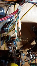
I have noticed what looks like a capacitor across one of the sets of contacts has a leg broken off. I tested one of the other bumpers by removing the capacitor to see if it made a difference and that bumper still fired fine without it.

Finally I checked continuity between the contacts that have the capacitor soldered to them. On the 2 bumpers that work my multimeter says no connection. On this bumper that isn't working and snapped capacitor it says there is continuity between those contacts which seems strange. I'd have thought the results would be the other way round.
Could it be a transistor that has died on the controller pcb causing this fault and the odd continuity results across those contacts?
 
Davey,

Apologies if I'm pointing out something you already know, but this game has what Williams used to call 'Special' solenoids. The last six solenoids have their drive transistors controlled directly from the playfield switches, rather than by the Cpu/program. The first that the cpu knows about it is after the solenoid has energised. They're usually used for Jet bumpers and slingshots, though some games have to call on spare ones for other duties.

Each bumper has a 'double' switch arrangement in the stack - the upper part, nearest the playfield, switches the transistor via some logic gates by pulling an input line to ground. A resistor and capacitor improve the sensitivity of this section. The lower part, which produces score, sound effect and any other outcome, is a normal 'matrix' switch, with isolating diode. This section is operated by the bumper linkage rather than the spoon blade.

It looks as if your game isn't driving the bumper coil, and so the reporting software hasn't seen the scoring switch for a while, hence the alert. That's one bonus with this set up, a non-functioning spec/solenoid brings up a report.

I don't think that Orange-green is a switch matrix wire; they're White w/trace colour and Green w/trace colour. Or/gn is more likely to be the transistor input line (the ground wire is Black).

I'd check that the switches are wired correctly. The special part should be Black, and Orange/trace, with the resistor/capacitor. The scoring switch should be White/trace and Green/trace, with diode. Then, with the machine in 'Switch Edges', momentarily energise the coil from the main board by grounding the metal tab of the relevant transistor in the top right corner of the pcb. The bumper switch, 21, should be shown.
 
Last edited:
Thanks for the input. Its still quite new to me figuring out what controls what with these machines. Ive been lucky so far in that all the other faults on my machines have been something physically broken / loose / missing so have been fairly easy fixes.

I double checked the wiring last night, and i was wrong with my colours. the colours i stated above are for the scoring switch which works fine if i manually puch the solenoid down to activate the switch.

The colours for the switch which activates the bumper are White + Orange/green

i.imgur.com_xmyhRU0.jpg

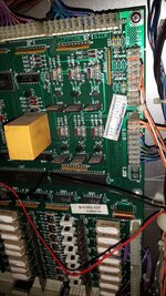
Ive traced them back to the PCB with the connector being 1J18. If i connect the white to either of the other 2 orage/trace wires it activates that bumper, but not the orange/green for the lower bumper.

i.imgur.com_dnbE7hN.jpg

With regards to the transistors im presuming its the bigger ones as seen in the picture, so i need to find out which one controls the lower bumper. Just scanning over them by eye Q75 looks like it has been replaced before as the solder hasnt flowed all the way through the hole to the top side of the PCB, and doesnt feel as strong in the hole as the others

Everything should be wired correctly as ive had the game around a year, and it has always worked fine until now. I did fit some LED to the machine a few weeks back, but it worked fine after doing that. I think its just a coincidence that this has happened around the same time.

Is it the top with the mounting hole that i need to ground on the correct transistor? if the switch shows up as working in the edge test does that likely mean that the transistor is dead and needs replacing?
 
Is it the top with the mounting hole that i need to ground on the correct transistor? if the switch shows up as working in the edge test does that likely mean that the transistor is dead and needs replacing?

Yes and Yes if it doesn't fire the solenoid when grounding it. If it works expect a nice spark! :cool:
 
Oh and if it's Q75 it could just be a case of reflowing the solder to go all the way through.
 
Ive just had another flick through the manual, and found what im looking for. I had been looking through the circuit diagrams for a few days, then found this on page 2 lol

i.imgur.com_rVUSqci.jpg

Looks like its Q77 that i need to be tresting then :thumbs:
 
Also does anyone know off the top of their head what model transistor i need to replace it with?
 
Black Knight 2000 doesn't have anything using 'Special #6', so (assuming it's okay) you could transfer its transistor, Q79. The component is what's called a 'Darlington' transistor (actually two devices connected in series), TIP 122.

I was mistaken about colours, too. I recalled the ground wiring for the special switches as Black, in this case it's White.
 
Ok, so I've tired showing q77 to ground in switch test. Switch 21 shows on the screen, and the bumper fires. Does this mean that the transistor is ok?
 
Have you put the game in switch mode and pressed the bumper skirt? does it register? If does then try it again this time using a ball, if it doesn't that is what your problem is...
 
Yes have tried it, and the switch doesnt register. the only time i get anything to register is if is push the solenoid down so that the points registering part of the switch makes contact. Ive even tried shorting the white and orange/green together at the plug on the PCB 1J18 (thus eliminating the physical switch as the fault) and it wont fire, yet if i short the other 2 bumpers at the plug then they will fire
 
Only other thing i can think of is checking the header pins on the connector are ok, as if the pin for this pop bumper is bad then it wouldnt fire when shorting it on the plug.

I take it that the wires in this harness should lead to the legs of the transistor, so before taking the board out of the backbox i should be able to do a continuity test from the pins to the transistor to check for breaks?
 
Is the pop bumper skirt sitting properly and activating the spoon switch properly? check the connections to the spoon switch. Does the spoon switch register if you operate it manually with the playfield up? Take care when doing this as the game will need to be powered up. Remember to remove the pinballs before lifting the playfield.

The wiring from the transistor is fine beacuse you check that when you grounded the transistor and the solenoid fired.
 
Ive had the upper mini playfield up with the game powered on all the time ive been testing it, just making sure i stay away from the shocking bits :D

If i put a multimeter across the switch contacts and push the skirt, or even if i close the contacts manually a continuity test shows fine. With the test i did on the PCB connector plug (that i mentioned above) didnt make the bumper fire, and that is just acting as the switch would, but eliminates the switch, and wiring to the switch as the fault as it doesnt fire when shorting the connector.

Are there any other components on the PCB before/after the transistor that could have failed causing it not to fire from the switch, or is it literally just wires in from switch to transistor, and then power out to the solenoid?
 
Yes, Davey,

The actuating switch (which isn't in the switch matrix) grounds an input of a logic 'gate' contained in one of the small chips nearby, possibly U 50. The output of the gate switches the 'pre-drive' transistor, which for Special #5 is Q76. The pre-driver switches the actual driver to energise the coil. (In later system 11 games with 50v coils, there's also a 3rd stage driver involved, on the 'Aux Power/Driver' board).
 
Is there any way to test the transistor at Q76 other than removing it? Since Q79 isnt used does that mean i could also pinch Q78 to try?
 
Or is it possible to move over the wiring on the switch in, and solenoid out wiring plug over to the unused special#6 ?
 
That's ingenious, Davey. Moving the switch input line to Special Switch 6, and the coil drive to Special 6 should work, if that circuit's alright. It's immaterial to the cpu which input/drive cause the bumper scoring switch to close. The only odd thing would be the solenoid test - the bumper coil would be energised under the heading #22 'Not Used' or 'Spare'.

The driver and pre-driver components are the same for Spec. 5 and 6, the non-exchangeable part is the gate circuit used (there are four built into each of the two chips, U45 & 50).

Update - having now looked at the schematic, each pre-driver/driver circuit with a load connected can be checked by momentarily raising the base of the pre-driver to 5v. A handy way to do this is to short across the base resistor, which is connected to the 5v line. For Special #5 (Q76/77) it's R 103, in the middle of the group of 3 resistors above Q 76.
 
Last edited:
So I finally got to work on this tonight. I moved the output wire from its original position to the special#6 output. Then I shorted Q79 to ground and the pop bumper fired! :-D

Next with a bit of trial and error (although was lucky to find it first go) I found the special#6 input and swapped the wire over. Powered the machine on and started a game.... now works perfect!

When I get more time after I've rebuilt my tftc I'll pull the cpu board out and swap out the original transistor to fix it properly
 
Back
Top Bottom