What's new
Pinball info

Register a free account today to become a member! Once signed in, you'll be able to participate on this site by adding your own topics and posts, as well as connect with other members through your own private inbox!

Bell Games SPACE HAWKS MPU Repaired for SWL

Nedreud

Registered
Joined
Feb 12, 2013
Messages
3,092
Location
Aldershot, UK
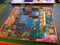
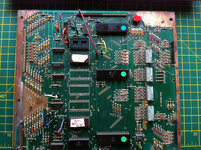
Hey, @Moonraker! Found some time today to give the MPU from your Bell Games' SPACE HAWKS a prod. Eek! What a mess! I don't know if this board ever worked since Peter's had it. All I knew was that the test LED was stuck permanently on.

First up I pulled all the chips and tested them one by one in a known-good MPU. They're all ok. As I didn't have the ROMs because they're in my GOLD BALL MPU currently installed in SPACE HAWKS at Special When Lit, I re-jumpered the board to work with the set of three 9316 ROMs from my PARAGON. As an FYI here are jumper settings beforehand:

SPACE HAWKS
E4-E12
E7-E8
E10-E11
E13A-E14
E16A-E34
E29-E33
E31-E32​

This configuration is for a game with ROMs U2 and U6 with either being type 2532 or 9332.

Obviously, re-jumpering the board wasn't going to fix anything, but at least I could remove all socketed chips and then re-seat just U6 (Game ROM), U9 (6800 CPU) and U11 (6821 PIA) as that is all that's needed to get the 1st flicker. LED light was still stuck on. The reset circuit was good as HIGH signal was present on pin 40 of the CPU, the clock signal was also good and I traced the VMA all the way through the board. Mmm... time to start probing track continuity...

I concentrated on the area around U11 and the LED because my hunch was that the board may have been booting but the LED control had failed. Eventually I found it. The socket for pin 39 from PIA U11 showed conductivity to pin 8 on connector J1 (CA2 lamp strobe) but not to resistor R28. This path controls the transistor Q2 that flashes the LED! Just beside the socket pin on the topside of the PCB there was a tiny break in the fine track that runs between pins 2 and 3 to R28. Bridged on the rear with some wire and voila! Flashes!
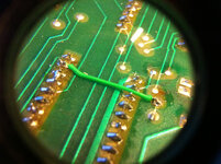

farm9.staticflickr.com_8582_16777095235_1004810803_c.jpg

The rest of the board needs a good overhaul as there is some decidedly dodgy soldering and track repair :eek:
 
Was that 6 flashes? coz IIRC you only need +43v solenoid voltage for the 7th... so it might be working... :eek: Great job Peter :thumbs:
 
Yes, only 6 flashes as it's on the bench with no +43VAC, just +5VDC and +12VDC. It's possible to simulate by bridging a connection to provide power to the ZCD (Zero Crossing Detector) circuit thus simulating a pulse. This is detected by U11 and gives the 7th flash.

@Moonraker, was this board ever working for you? Did you test it in game or just on the bench and because of the LED assume it wasn't working? It might not still be 100% functional in terms of I/O but TTBOMK the CPU is up and running, and all the ROM/RAM is passing the tests. I plan to make it down to SWL in a couple of weeks so we can try it out. I am right in thinking the ROM is one of those jobbies on a daughter board that sits on J5? There was a wire on the back of the board that connected a pin com the 6800 CPU to the last unused pin on J5. Is this a mod for the daughter board? Can't see that it is else my GOLD BALL MPU wouldn't work without it.
 
@Moonraker, was this board ever working for you? Did you test it in game or just on the bench and because of the LED assume it wasn't working? It might not still be 100% functional in terms of I/O but TTBOMK the CPU is up and running, and all the ROM/RAM is passing the tests. I plan to make it down to SWL in a couple of weeks so we can try it out. I am right in thinking the ROM is one of those jobbies on a daughter board that sits on J5? There was a wire on the back of the board that connected a pin com the 6800 CPU to the last unused pin on J5. Is this a mod for the daughter board? Can't see that it is else my GOLD BALL MPU wouldn't work without it.

The board worked in the game for a good 2 or 3 years and it survived weekends at the UK Show and South Coast Slam. It died in game and I thought it might be one of the chips life expiring or a small bit of corrosion somewhere causing upset. The LED was always locked on, I wondered if it was a bell game specific until you mentioned that you knew where to look. Yes, bell games use the ROM on the daughter board that sits on J5 and the mod is probably daughter board specific but can't say for definite.
 
Yes, bell games use the ROM on the daughter board that sits on J5 and the mod is probably daughter board specific but can't say for definite.
I can't remember... did you put the daughter board on my GOLD BALL MPU? If so, then the extra wire must have been a repair not a mod else it wouldn't have worked.

Mystery solved. RTFM. The MPU schematic shows that pin 24 of the CPU is address line A14 and pin 33 on J5 (not unusued, my mistake) is also marked A14, so the wire must be a track repair although there is no direct path between the two pins (it must take a roundabout route on the board).

Unfortunately I can't test the board in PARAGON as it's been completely stripped for restoration. I could re-jumper it for GOLD BALL but that's only partially rebuilt and it doesn't have working sound so not the best test machine! I could re-jumper for VECTOR and test it in that? Or I could do my header pin mod on the E points and then use the jumper wires to make it easily reconfigurable for any ROM/EEPROM combination?
 
I can't remember... did you put the daughter board on my GOLD BALL MPU? If so, then the extra wire must have been a repair not a mod else it wouldn't have worked.

Yes, daughter board was fitted to your MPU.

Mystery solved. RTFM. The MPU schematic shows that pin 24 of the CPU is address line A14 and pin 33 on J5 (not unusued, my mistake) is also marked A14, so the wire must be a track repair although there is no direct path between the two pins (it must take a roundabout route on the board).

Cool. :cool:

Or I could do my header pin mod on the E points and then use the jumper wires to make it easily reconfigurable for any ROM/EEPROM combination?

That fine with me. :D
 
Modified! I had the pleasure of attending a 2.5 hour teleconference meeting during which I spoke once, so I spent the rest of the time listening and working on the MPU!

farm8.staticflickr.com_7642_16598941158_6cd33e1f19_c.jpg

Tested on the bench with PARAGON ROMs and still getting 6 flashes, so next I'll swap it into VECTOR and see if it can actually run a game!
 
I'm very alert to what's being said! I have to be, it's part of my job. But it ended up that much of the meeting wasn't about the stuff I work on. Mainly because stuff I work on is either working, finished, in testing or fully understood and documented and needs no further discussion ;)

Soldering is also very therapeutic whilst on a teleconference call :D
 
the women doing most of the talking had such a loud voice I could hear her from the toilet no problem
That's made me laugh out loud!

Me too! I hope you weren't too loud on the toilet that she could hear you :eek:

Back on the subject of pinball... @Moonraker, I swapped my VECTOR EEPROMs into the SPACE HAWKS MPU this morning and re-jumpered it using the new jumper pins and wires. One nice side effect of this test is that I discovered my VECTOR board has been incorrectly jumpered. It has a pair of 2732 EEPROMs in U2 and U6. For this, one of the jumpers should be E12-GND. This is unusual as all other jumper configuration are E-pin to E-pin. But on my VECTOR it's been wired E12-E9. E12 is the CS (CHIP SELECT) on to U1 and U2, whilst E9 is connected only to the CPU address line A11. As U1 is not used in this configuration I guess it makes sense to tie the CS to GND and maybe it just so happens that in this configuration A11 is always held low? Anyway, I'll fix that on my VECTOR board by adding a header pin on E12 and using a jumper wire to connect it to J5-31 which is GND.

Here's your MPU jumpered for VECTOR, note the red jumper from E12 to J5-31 for the GND connection:

farm8.staticflickr.com_7620_16791698671_2738211c10_c.jpg

VECTOR - U2, U6 = 2732
======================
E4-E13A
E7-E8
E9-E12 (Wrong! Should be E12-GND)
E10-E11
E16A-E29
E31-E32
E33-E35


Popped it back into VECTOR with just J4 connected for power and switched it on... Woohoo! 7 flashes. Switched off again and re-connected J1, J2 and J3, and powered it back up...

"I AM A P.A.C. - PLAY ANALYSIS COMPUTER - FOR YOUR VECTOR GAMEPLAN!"

Sweet! Played a few games and all seems to be well.

One thing I did forget to do was write down all the DIP switch settings before I changed them to be the same as VECTOR :( but then I remembered I took a photo so here they are! :)

S1 OFF
S2 OFF
S3 OFF
S4 OFF
S5 OFF
S6 ON
S7 ON
S8 OFF

S9 OFF
S10 OFF
S11 OFF
S12 OFF
S13 OFF
S14 OFF
S15 OFF
S16 ON

S17 ON
S18 ON
S19 ON
S20 OFF
S21 ON
S22 OFF
S23 OFF
S24 OFF

S25 ON
S26 ON
S27 ON
S28 ON
S29 ON
S30 ON
S31 ON
S32 OFF
 
Interesting. We know the daughter board is working ok and that board is now working ok with the Vector ROMs, therefore the fault must lie with J5 connector or the data lines feeding J5.
 
I'll trace the J5 lines for continuity. We know at least one is bad due to the wire. The pins are also a bit grotty. Will give them a little Dremel love :D
 
Okay, more research. Checked all the pins on J5.

When I got the board there was a wire on the rear from pin 24 of the CPU (address line A14) to pin 33 on J5. Strangely, this path is working fine without the wire. However, using a 3.5x eye-piece I noticed there was a solder bridge between J5-33 and J5-32. This pin runs to pin pin 18 on PIA U11 (CB1). Can't imagine this was helping the daughter board!

But I did find a break between pin 27 on the CPU (U9) and J5-2. This is data line D6. It's a dry solder joint, so quite probably intermittent with the weight of the daughter board hanging from it. Probably going to get some pretty erratic operation with only 7 bits of data :eek:
 
Back
Top Bottom