What's new
Pinball info

Register a free account today to become a member! Once signed in, you'll be able to participate on this site by adding your own topics and posts, as well as connect with other members through your own private inbox!

Bally Xenon - Sound issue

waynej4

Registered
Joined
Oct 10, 2020
Messages
194
Location
South Norfolk
Hi All,

Hoping someone has some suggestions on the sound issue with my Bally Xenon.

When I power on the pinball machine or play a game, there is no sound whatsoever. When I push the test switch on the sound board, It produces the voices and sound effects (cycles through them).

Things I've tried so far:

Checked continuity from J1 connector on sound board to all the other connectors it connects to (seems okay to me).
Replaced all the caps on the sound board.
Replaced the 3 x diodes on the Vocaliser board
Reflowed all the connectors on the Solenoid/Driver board and the sound board
Replaced the large cap on the Solenoid Driver board,
Replaced U5 (4049) and U6 (4093) IC's on the Sound board.

I'm assuming, as I can hear the sounds when pressing the test button, that the Vocaliser board and its Roms are fine.

To me, it seems as if the Sound board isn't being "Told" when/what sounds to play.

Any suggestions on where/what to look at next appreciated!
 
have you changed setting 18 to 03 to select all sounds during play?
 
Hi.

Yes, changed setting 18 to 03. Forgot to mention that.

Pressing the test from the coin door red button produces no sound.

Also, should have mentioned. The pot in the door does seem to work. Does change the volume when the sound is activated from the test switch.

Kind regards,
Wayne.

Sent from my Commodore 64 using Tapatalk
 
I'll give that a once over. Any ideas on which bit ?
[emoji854]

MPU board is a replacement Alltek board.

Sent from my Commodore 64 using Tapatalk
 
that should not need a reflow if it's an alltek,it must be the connectors
 
my money is on the header wiring j4 from mpu and j1 also has one wire to sound board. the same control wires from j4 mpu also used for solenoids and so also go to the sdb too. unplug sdb connection to rule out any issues with it interfering with the signals.
 
  • Like
Reactions: DRD
I've tested connectivity to all wires now between MPU J4 and SB, between SB and Solenoid board, and between Solenoid and MPU. Can't find anything amiss.

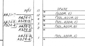
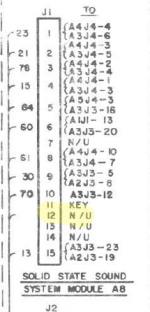
For the J1 from MPU, I have no connection to the SB. In the Sound board wiring diagram it mentions MPU J1 Pin7 to SB J1 Pin12. I have nothing in Pin12.

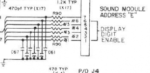
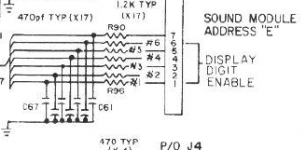
Looking at the MPU wiring diagram, it shows that J1 Pin 7 should be one of the display digit enable pins - and it does go off to the first display in the backbox. So confused why Pin12 on SB shows connection to this pin. also the wiring diagram shows Pin12 is not used!

1619795012672.png 1619795083669.png
Sound board (J1) - Note pin 12 says to MPU J1 P7 / Connector Wiring J1 Pin 12 - N/U

MPU also mentions "Sound Module Address E", though - which is pin12 on the SB !

1619794844411.png
 

Attachments

  • 1619794987539.png
    1619794987539.png
    11 KB · Views: 1
Can you board swap with another machine?

Did the sound ever work properly under your ownership ? Or did you buy a project ?
 
pin 7 is not used on the sounds plus board,pretty sure the trace goes to nowhere from the header pins
 
pin 7 is not used on the sounds plus board,pretty sure the trace goes to nowhere from the header pins


Pin 7 on the SB is not used. It is Pin12 I'm confused about - that says it is connected to J1P7 on the MPU. Well, on the SB schematic it says that on the Connector schematic it says not used. And I don't have any wires in pin12 on the SB.

Can you board swap with another machine?

I can't, unfortunately. It was a project. My thought is the SB is working (works when I press the test button), but not getting the "commands" to activate the sounds when it needs to (or it is getting the commands, but not sending it on/processing correctly - which implies it is only partially working! Arrrrggghhh!!!).
 
Sorry if daft, but have you correctly selected Xenon on the Altek board ? Worth a double check.

Next ports of call for me would be:

1. Cleaning the pins on the sound board with very fine emery paper followed by ipa solvent
2. Rebuilding the connectors between MPU and sound board
3. Find someone local to you to boardswap with
4. Burn it

These old connectors are an absolute nightmare.

My Centaur has needed connectors rebuilding but I have been too lazy. It has managed league meetings, booting it twice normally does the job.

The other day it booted, all seemed well, it had 40 credits, but the game would not start.

I spent ages messing about with switch tests.

Somewhat remarkably, it transpired that the relevant connector on the mpu had failed relating to the start button !!!!
 
No, not a daft suggestion - I did check the Dip switches for correct pin selection, and then checked again and again!

I think I'll have to move on to Step 2 - rebuilding all the connectors.
Or, alternatively, if there is someone in the Kent area that can do a board swap.... :-)
I'm not hacked off enough yet to consider option 4! (although 20yrs ago, I would have run out of patience ages ago!!).

@stevebm1 thanks for the photo - confirms your connector looks the same as mine!
 
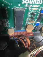
opened my backbox and took a pic for you,hope that helps

View attachment 137428
Hello from France!!!
do you have checked the sound Board J1 pin 8 signal (sound Interrupt)
I think I see ref.61 (it's mean Brown/Red wire color)
if not activated no sound will be heard...
you can slide the black cover of the J1 connector to see the state of the wire crimping because that type of connector is not very good quality
Lionel
 
Last edited:
  • Like
Reactions: DRD
Hello, France! [emoji3]

What do you check on pin 8? I've checked it connects to wherever it goes to at the other end of the wire. Is there something else you specifically check?

Kind regards,
Wayne.


Sent from my Commodore 64 using Tapatalk
 
if you don't have an Oscilloscope it's difficult to help you more!
but when you check signal continuity prefer to check directly on R14 to R18 (or U2 pin 40 for "sound Interrupt")
and not only on the J1 connector (to include all bad contact on connector crimp or some dry welding problem)
good luck
 
Last edited:
Got it!

Looks like the Sound chip AY-3-8910 (U1) is the issue. I've replaced it with a Yamaha YM2149F, and sound is back!

Apparently this IC is equivalent to the Bally sound chip (not a 100% match, but nothing that is an issue with this game, I believe).

I took a punt that it may be this chip as someone on a Pinside thread from a few years back had mentioned that he'd replace U4 (CD4049), and his sound returned. This is, apparently, not used when using the test button, but comes in to play when using the game. I replaced my 4049 IC, but this didn't resolve it for me. On the schematics, this feeds in to a handful of pins on the sound chip, so thought that this may be the next logical step to try (and the IC itself was only a few quid).

Anyway, thanks everyone for the suggestions. I think I'm still going to redo the connectors, as I can see them being an issue later on down the line!

Thought I'd post my solution in case it is helpful to someone else in the future.
 
Great news. Very pleased for you. These old Ballys can be fickle mistresses
 
Back
Top Bottom