Is that one below the window hiding so it can't be seen from outside?
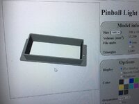
Pinball info
You are using an out of date browser. It may not display this or other websites correctly.
You should upgrade or use an alternative browser.
You should upgrade or use an alternative browser.
In Progress Bally Vector - Serial Number: EVE2999
- Thread starter 8bit-1up
- Start date
If they're the two from Facebook at £400 each you did well!
Sent from my Atari 2600
Sent from my Atari 2600
were they the two from facebook market place for £800?,if so you got a good deal
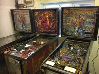
Yes these are the Pinball machines from Facebook, the seller originally offered me all three for £1400, but I only really wanted the Medusa. He ended up changing his mind and decided to keep Playboy and try and restore it himself. I ended up getting both Medusa and Vector for £700 in the end - he said he was tired of being messed about by people promising to buy Vector and not showing up and then offered me both for £700. I wasn't planning on having 2 Vectors, but he made me an offer I couldn't refuse! He seemed like a really nice guy, he knew how much they were both worth, but just wanted them gone so he could start work on his Playboy.
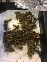
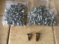

Decided to coat the hinges in zinc to stop anymore rusting. I used a Dremel to get ride of the rust and smooth everything out, and then coated the hinges with three coats of zinc spray.
Attachments

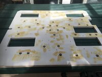
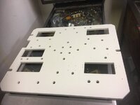
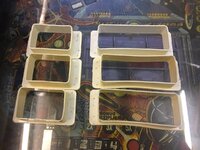
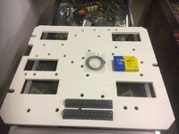
Head box bulb holder board sanded, filled and painted.
Attachments
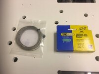
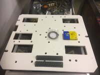
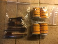
what size wire you use for the lamps please? need to get some ordered for my paragon refurb / pf swap
what size wire you use for the lamps please? need to get some ordered for my paragon refurb / pf swap
Hey Alan,
It’s the same wire you recommended to Rudedog1.
Round tinned copper braid 0.75 mm2 ( 1.3 mm dia nominal) 15 Amps – Copper Braid Products
AHa, I totally forgot about that. thanks, just ordered!
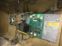
Had problems getting Vector to boot up properly with the Alltek MPU, so decided to try another MPU and see if that fixes the issues.
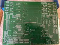
I’ve gone for the open source Lisy35 board this time. Seems to have a few more options than the Alltek board. The wireless and sound card options look very interesting.
The boards cost roughly £45 to build, so are definitely a good option if you are on a budget.
I’ve finished building the first board, so will report back soon with an update.
Attachments
Last edited:
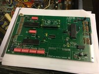
Eureka! Booted up first time! I now have two booting Vectors.
Freeplay and player option both work perfectly.
I don’t know what the issue is with the Alltek MPU? I might try and fix it at a later date, but for now, I’m very happy with the Lisy35 boards. I have also ordered the sound card PCB to try out.
Freeplay and player option both work perfectly.
I don’t know what the issue is with the Alltek MPU? I might try and fix it at a later date, but for now, I’m very happy with the Lisy35 boards. I have also ordered the sound card PCB to try out.
Attachments
Last edited:
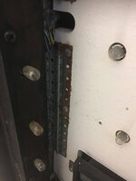
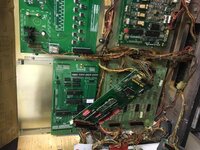
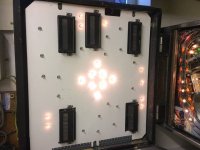
I almost have a completely working Vector - the only issue left to fix is the GI lights in the backbox.
Tested the 6.5AC on the bare wire and all seems good there, also tried for shorts on the bulb fittings and they all seem good.
Here’s a list of everything I’ve checked so far.
1. Fuses = all good
2. 6.5V on bare wire = all good
3. Shorts on bulb fittings = all good
4. Bulbs = all good
5. TP4 6.5AC checked on power supply board = all good
The only thing left I can think of is a grounding issue?
Any suggestions would be greatly appreciated.
Attachments
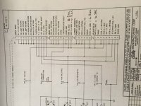
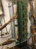
Check for broken connector pins, you've already identified which ones to look at.
Checked continuity and 6.5V everything checks out? This is really beginning to be a bit of a head scratcher? I know the backbox GI lights only come on once a game is started and don’t come on during demo mode.
Not worked on a vector for a while...so working from memory. (Disclosures, I am a forgetful ole duffer!).
Couple of things to check. 1).Solenoid expander pcb. (Relay check, connectors check, check for dry solder joints.).
2). Lamp flasher driver. 3). Lamp driver connector pin a5j3.1 and worth checking a5j3.26 For starters.....
All the best Keef.....(oh and when I get 5 I will dig out the manual for more of an educated diagnosis....).
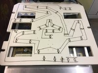
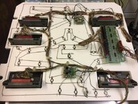
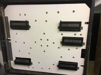
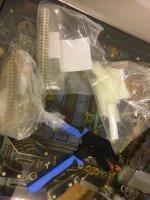
It’s crimping time!
Time to say goodbye to those temperamental IDC connectors and replace them with the more reliable molex variety.
Time to say goodbye to those temperamental IDC connectors and replace them with the more reliable molex variety.
Attachments
Last edited:
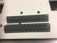
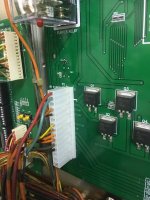
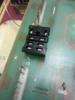
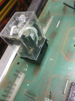
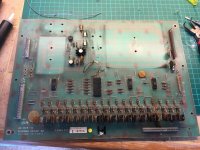
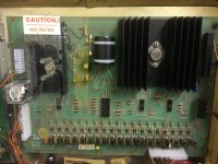
Decided to rebuild and repair the original solenoid driver board. Added a new relay with a socket to help with maintenance in the future.
Attachments
Last edited:
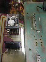
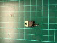
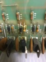
Added a new 1N4007 diode, 330ohm resistor and TIP102 transistor where the old burnt out components were. Also added new caps.
Attachments
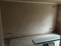
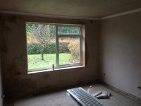
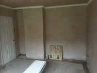
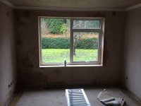
The missus has given me permission to have my own pin room!
The new plaster is drying nicely - hopefully should have the room painted by the weekend.
The new plaster is drying nicely - hopefully should have the room painted by the weekend.