Working on a Bally / Stern SDB - Solenoid Driver Board Tester.
This follows on from the Lamp Driver Tester board I did a couple of years ago:
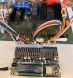
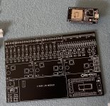
Here is my V1.0 Prototype Tester Board:
.png") board design (resized).png
board design (resized).png
It will test:
1. The 15 Momentary Solenoid Driver Circuits, Q1-Q14, Q16
2. The 4 Continuous Solenoid Driver Circuits (Including the Coin Lockout and Flipper Enable Relay) Q15, Q17-Q19
3. The Two Flipper Relay Switch circuits
4. The 5v Regulator Circuit
5. The HV circuit
There will be an option to still be able to test, even if the SDB 5v regulator circuit has failed. (By providing 5v supply to the SDB from the tester itself, instead of from the SDB).
Prototype board is in production and should arrive in a couple of weeks.
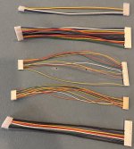
There are 5 Jumpers on the SDB board, with a ton of connections. The tester needs 39 connections to the board in order to run all the tests, so the main complexity for this project is making up 5 separate wiring harnesses. J1,J2,J5 are 3.96mm and J3,J4 are 2.54mm.
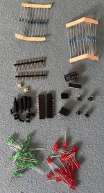
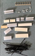
J3 is a 25 pin housing which are not easy to get ahold of. I got some 3D printed in Nylon to a design specification that allows them to house the Molex 2.54mm HIGH PRESSURE Crimps - these make a really good contact with the pins, much better than the standard crimp pins - but also 20X the cost! (We don't really need this level of quality for this tester, but given these are the only 25P housing I have available, I'll use it).
I've already started working on the code:
1. Start up - reset all outputs and initialise the LCD display, display Opening Message and firmware Version No. for 2 seconds.
2. 5V test - If the 5v regulator on the SDB is generating 5V the "5v SDB Test" Led should be lit. No other leds should be lit on a working board.
3. Lock On test - Display a message warning that any lit "Q" number Led means the corresponding driver transistor/circuit is faulty and locked on. These should be fixed before proceeding any further.
4. All Q Test - will flash all the Q circuits quickly in sequence. If a Led doesn't flash, it's a faulty circuit.
5. Q Number test - Runs through each Q number from Q1 to Q19 and flashes the corresponding Led. If the Led doesn't flash then the drive transistor/circuit is faulty and should be fixed.
Q15 is the Flipper enable relay. The Tester will test both relay switches for the left and the right flippers, so both Q15 Leds should light whilst Q15 is being tested, the flipper enable relay should also click on and off and be audible as it does so.
6. HV Test - At any time the user can press the "Test HV" button on the right hand side of the unit to test the SDB High voltage circuit. If the circuit is operational, the "HV test" LED should illuminate when the test button is held down. it will go off as soon as the button is released.
The Momentary Solenoids are Q1-Q14 & Q16 (15 of them) are controlled by the 74L154 IC. If this is faulty then expect to see issues with these Q circuits.
The Continuous Solenoids are Q15, Q17, Q18, Q19 - these are directly controlled by the MPU in the game.
The HV test is conducted using the highest voltage we have on the tester board which is the "43v" circuit. In reality, this is going to be less than 40v because the buck boost circuit boards I am using can only generate around 39v max. I have labelled the circuit 43v just to be compatible with the nomenclature in the Bally/Stern schematics.
The HV circuit is usually powered by 230V DC, but I didn't want to have such a high voltage on my tester board. I have tested a few on my boards (good ones and faulty ones) and they all worked at the lower voltage of around 40v. i.e. a faulty circuit didn't light the Led and a good circuit did!
The wiring harnesses will consist of 5 cables from the tester to the SDB, J1-J5: Here is the mapping:
.png") pasted_image2 (resized).png
pasted_image2 (resized).png
If this all works, I'll make kits available. Probably 2 options:
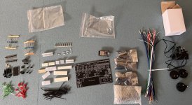
1. Tester Kit + Harnesses : Full kit to make up the tester board plus all the parts to make up the 5 wiring harnesses.
2. Tester Kit : Full kit to make up the tester board, but without the wiring harnesses.
I'll update this thread once I've got the PCB in hand.
This follows on from the Lamp Driver Tester board I did a couple of years ago:
Any Interest in a Bally SS Lamp Driver Board Tester?
I've been thinking for a while about building a bally lamp driver board tester for the Bally Lamp driver boards ( AS-2518-23, AS-2518-14, Stern LDB100). Up to now, I've always tested a board in a game, but the problem is that not all games use all the circuits (especially the older games)...
www.pinballinfo.com
Here is my V1.0 Prototype Tester Board:
It will test:
1. The 15 Momentary Solenoid Driver Circuits, Q1-Q14, Q16
2. The 4 Continuous Solenoid Driver Circuits (Including the Coin Lockout and Flipper Enable Relay) Q15, Q17-Q19
3. The Two Flipper Relay Switch circuits
4. The 5v Regulator Circuit
5. The HV circuit
There will be an option to still be able to test, even if the SDB 5v regulator circuit has failed. (By providing 5v supply to the SDB from the tester itself, instead of from the SDB).
Prototype board is in production and should arrive in a couple of weeks.
There are 5 Jumpers on the SDB board, with a ton of connections. The tester needs 39 connections to the board in order to run all the tests, so the main complexity for this project is making up 5 separate wiring harnesses. J1,J2,J5 are 3.96mm and J3,J4 are 2.54mm.
J3 is a 25 pin housing which are not easy to get ahold of. I got some 3D printed in Nylon to a design specification that allows them to house the Molex 2.54mm HIGH PRESSURE Crimps - these make a really good contact with the pins, much better than the standard crimp pins - but also 20X the cost! (We don't really need this level of quality for this tester, but given these are the only 25P housing I have available, I'll use it).
I've already started working on the code:
1. Start up - reset all outputs and initialise the LCD display, display Opening Message and firmware Version No. for 2 seconds.
2. 5V test - If the 5v regulator on the SDB is generating 5V the "5v SDB Test" Led should be lit. No other leds should be lit on a working board.
3. Lock On test - Display a message warning that any lit "Q" number Led means the corresponding driver transistor/circuit is faulty and locked on. These should be fixed before proceeding any further.
4. All Q Test - will flash all the Q circuits quickly in sequence. If a Led doesn't flash, it's a faulty circuit.
5. Q Number test - Runs through each Q number from Q1 to Q19 and flashes the corresponding Led. If the Led doesn't flash then the drive transistor/circuit is faulty and should be fixed.
Q15 is the Flipper enable relay. The Tester will test both relay switches for the left and the right flippers, so both Q15 Leds should light whilst Q15 is being tested, the flipper enable relay should also click on and off and be audible as it does so.
6. HV Test - At any time the user can press the "Test HV" button on the right hand side of the unit to test the SDB High voltage circuit. If the circuit is operational, the "HV test" LED should illuminate when the test button is held down. it will go off as soon as the button is released.
The Momentary Solenoids are Q1-Q14 & Q16 (15 of them) are controlled by the 74L154 IC. If this is faulty then expect to see issues with these Q circuits.
The Continuous Solenoids are Q15, Q17, Q18, Q19 - these are directly controlled by the MPU in the game.
The HV test is conducted using the highest voltage we have on the tester board which is the "43v" circuit. In reality, this is going to be less than 40v because the buck boost circuit boards I am using can only generate around 39v max. I have labelled the circuit 43v just to be compatible with the nomenclature in the Bally/Stern schematics.
The HV circuit is usually powered by 230V DC, but I didn't want to have such a high voltage on my tester board. I have tested a few on my boards (good ones and faulty ones) and they all worked at the lower voltage of around 40v. i.e. a faulty circuit didn't light the Led and a good circuit did!
The wiring harnesses will consist of 5 cables from the tester to the SDB, J1-J5: Here is the mapping:
If this all works, I'll make kits available. Probably 2 options:
1. Tester Kit + Harnesses : Full kit to make up the tester board plus all the parts to make up the 5 wiring harnesses.
2. Tester Kit : Full kit to make up the tester board, but without the wiring harnesses.
I'll update this thread once I've got the PCB in hand.