What's new
Pinball info

Register a free account today to become a member! Once signed in, you'll be able to participate on this site by adding your own topics and posts, as well as connect with other members through your own private inbox!

Bally SS Coin Door Red Button Test Switch - Centaur

DRD

Site Supporter
1 10 Years
Joined
Oct 26, 2014
Messages
5,633
Location
Newark
This has just failed so I can't get into the test mode to adjust settings.

The game is otherwise fully working.

The actual switch has 5v DC across it (just like my working Fathom) and the switch itself works properly when tested with a multi meter.

It does not look like it is part of the regular switch matrix.

How does it work pls ? Where do the wires end up in the backbox ?

Thanks
 
This has happened to me a couple of times, for me it was the yellow and red wire on J2 on the sol board (it also goes to the switch on the coin door ) the crimped connection had Disintegrated , the only way I found out that is when I Unconnected it out of the molex it fell apart in my hands
 
  • Like
Reactions: DRD
This has happened to me a couple of times, for me it was the yellow and red wire on J2 on the sol board (it also goes to the switch on the coin door ) the crimped connection had Disintegrated , the only way I found out that is when I Unconnected it out of the molex it fell apart in my hands
good point. yes the ground comes from
there. what a silly way to wire it up.
 
good point. yes the ground comes from
there. what a silly way to wire it up.
First time this happened was on nitro ground shaker , it took me ages to work it out ,but when it happened on space invader I went straight to it and the same thing happened ,both Occasions looked perfect until I disconnected out of the molex
 
  • Like
Reactions: DRD
Brilliant advice, thank you all.

The switch wires are obviously a smaller gauge than the solenoid ones.

So by sending one of the switch wires to the solenoid board it was terminated in the larger size solenoid connector (0.156") versus the usual 0.1" for the MPU board

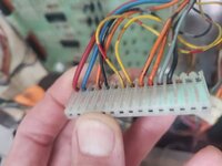
Over time the yellow and red, pin 7, looks like it has given up the ghost and is now a bit loose.

20220503_214736.jpg

Will replace this with a crimp connector.

I don't automatically do this for fear of causing collateral damage ....... but there really is an argument for biting the bullet and

1. replacing the connectors
2. reflowing every pin

on these old SS Ballys during your first week of ownership, or as soon as you have got them working.
 
Back
Top Bottom