Hello all,
I picked this machine up non working from an estate sale and have gotten most everything going but i have hit a snag. This is my first dive into bringing a machine back from not working. I currently own multiple machines but no major repairs under my belt.
A little context here, I was helped along with a Bally Night Rider "rebuild" and this means hand held through it. I was not there when the solenoid driver board and lamp driver board got components replaced and re-pining was done.
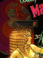
Now this Mata Hari when i picked it up they had it plugged in and turned on!! They thought this meant it was working. HA Half of the GI was on and half of the back box lights were on. I have gotten everything working except the flippers and the rest of the GI lights and the insert lighting. Below i will go through what i have done and i am looking to get ideas on where to go from here.
I replaced the MPU with a new Altek and this got the switches working but no coils would fire. I tracked this down to the fuse holder under the playfield and had to replace the entire unit. Now all of the coils fire during test mode. (Flippers are not activates during this test) I started a game and no flipper activation. i checked the switches and coils would fire (Slings, thumper bumpers, and kick outs) I did have 2 bumpers activating at the same time but gaping the leafs corrected this.
Flipper troubleshooting actions:
I tested with multi-meter again at all test points and everything checked out.
I am getting 39 volts at the lug on flipper coils
I grounded the flippers out and they fire
I then pulled the known good boards from my night rider for both SDB and LDB and this did absolutely nothing. So i installed the boards from Mata into Night rider and it played a game flawlessly and every light works. Not a board issue there
I took an alligator clip and clipped the end of stroke switches closed and still nothing happened
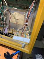
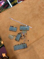
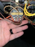
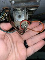
I have looked at pictures and diagrams and it appears they are wired correctly even though one looks like a crap show of a soldering job. (I will most likely still redo this)
I have been trying to track a possible grounding issue but nothing has made alight go off in my head.
What am I missing or over looking?
The lighting issue, I have yet to even try to figure out. During all of this testing for the flippers the inserts started working once but never again. Im sure this is just a connector most likely but the other half of the GI and bumpers not working is something entirely different it seems.
Any help or suggestions would be most appreciated.
I picked this machine up non working from an estate sale and have gotten most everything going but i have hit a snag. This is my first dive into bringing a machine back from not working. I currently own multiple machines but no major repairs under my belt.
A little context here, I was helped along with a Bally Night Rider "rebuild" and this means hand held through it. I was not there when the solenoid driver board and lamp driver board got components replaced and re-pining was done.
Now this Mata Hari when i picked it up they had it plugged in and turned on!! They thought this meant it was working. HA Half of the GI was on and half of the back box lights were on. I have gotten everything working except the flippers and the rest of the GI lights and the insert lighting. Below i will go through what i have done and i am looking to get ideas on where to go from here.
I replaced the MPU with a new Altek and this got the switches working but no coils would fire. I tracked this down to the fuse holder under the playfield and had to replace the entire unit. Now all of the coils fire during test mode. (Flippers are not activates during this test) I started a game and no flipper activation. i checked the switches and coils would fire (Slings, thumper bumpers, and kick outs) I did have 2 bumpers activating at the same time but gaping the leafs corrected this.
Flipper troubleshooting actions:
I tested with multi-meter again at all test points and everything checked out.
I am getting 39 volts at the lug on flipper coils
I grounded the flippers out and they fire
I then pulled the known good boards from my night rider for both SDB and LDB and this did absolutely nothing. So i installed the boards from Mata into Night rider and it played a game flawlessly and every light works. Not a board issue there
I took an alligator clip and clipped the end of stroke switches closed and still nothing happened
I have looked at pictures and diagrams and it appears they are wired correctly even though one looks like a crap show of a soldering job. (I will most likely still redo this)
I have been trying to track a possible grounding issue but nothing has made alight go off in my head.
What am I missing or over looking?
The lighting issue, I have yet to even try to figure out. During all of this testing for the flippers the inserts started working once but never again. Im sure this is just a connector most likely but the other half of the GI and bumpers not working is something entirely different it seems.
Any help or suggestions would be most appreciated.
 This also made the other half of the GI come on by putting the connectors on only half way.