Great news but please forget J9 pin 1 just for now. First you need to:
1. Unplug the table and check that you have continuity from one blue transformer wire to the CR2 Bridge rectifier and the other Blue wire and the F2 holder.
2. Check F2 is good - pull it out to do this never trust fuse tests in the holder, put it back
3. Then check the other side of the F2 fuse holder, violet / black wire which should also go to the CR2 bridge
4. Plug it in switch on and you should definitely find the 11v AC from the transformer across the CR2 bridge rectifier between the Blue and Violet/Black connections. So check the DC volts across the other two Orange/Blue (+) and Yellow/Black (-) wire connections to that bridge they should read ~16v give or take. If there is no DC voltage there then either the bridge is dead or its been replaced with the wires on the wrong pins.
5. Those wires go directly to either side of C1 the 4500uF Capacitor - there are a couple of big caps so you are looking for the one with the Orange/Blue (+) and Yellow/Black (-) wire connections again
6. Check for the same voltage again across the Orange/Blue (+) and Yellow/Black (-) wire connections on Pins 3 & 4 of J21
7. Check again that the voltage is coming out of the Orange/Blue (+) and Yellow/Black (-) wire connections on Pins 3 & 4 of P21 which should be plugged into J21
8. Now you have arrived at P9
")
so check the Orange/Blue (+) and Yellow/Black (-) wire connections on Pins 1 & 2 of P9 have 16v
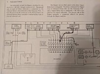
Here's the diagram again, we are talking about the bit in green:-