What's new
Pinball info

Register a free account today to become a member! Once signed in, you'll be able to participate on this site by adding your own topics and posts, as well as connect with other members through your own private inbox!

Apollo 13 moon magnet board.

taz turbo

Site Supporter
5Years
Joined
Nov 3, 2017
Messages
675
Location
Southport UK
Hello Folks,

Using a bit of the lockdown time to take a look at the moon magnet issues on my A13.

Situation I have is a repeated blowing mosfet on the board, the magnet coil measures good at 4.3 ohms, changing the mosfet and testing in coil test in hold (I believe this is 10% duty cycle) and the magnet pulses as expected and retains the ball. However if I put it into grab (100% duty cycle) the mosfet instantly fails and locks on. I wondered even with the coil testing good could there be an insulation breakdown, so replaced the coil, same symptoms!

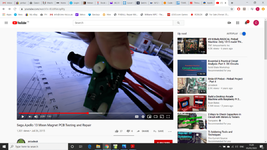
Doing a little digging on the internet and I came across a thread on Pinside, where there is an additional diode and resistor retro fitted to the track side of the board, from there I ended up on YouTube , someone in the UK testing and repairing the same board, it also has had the diode and resistor fitted.

Pinside...
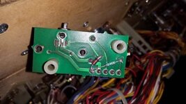
moon magnet board modification.jpg

YouTube...
Screenshot (10).png

Iv'e searched for technical bulletins, found a few A13 related, but nothing about this board/mod. The machine has had this fault since I've had it and NOT got the diode/resistor fitted. Does anyone know anything about this modification.

I disconnected the coil and fitted a lamp in its place and it all works as expected in test mode, obviously significantly greater resistance in the lamp than the coil.

My head is starting to hurt from banging against the wall now! Any help would be much appreciated.

Chris.

Edited to say ‘greater resistance’ in the lamp NOT less! 🤪
 
Last edited:
Hello Folks,

Using a bit of the lockdown time to take a look at the moon magnet issues on my A13.

Situation I have is a repeated blowing mosfet on the board, the magnet coil measures good at 4.3 ohms, changing the mosfet and testing in coil test in hold (I believe this is 10% duty cycle) and the magnet pulses as expected and retains the ball. However if I put it into grab (100% duty cycle) the mosfet instantly fails and locks on. I wondered even with the coil testing good could there be an insulation breakdown, so replaced the coil, same symptoms!

Doing a little digging on the internet and I came across a thread on Pinside, where there is an additional diode and resistor retro fitted to the track side of the board, from there I ended up on YouTube , someone in the UK testing and repairing the same board, it also has had the diode and resistor fitted.

Pinside...
View attachment 107124

YouTube...
View attachment 107125

Iv'e searched for technical bulletins, found a few A13 related, but nothing about this board/mod. The machine has had this fault since I've had it and NOT got the diode/resistor fitted. Does anyone know anything about this modification.

I disconnected the coil and fitted a lamp in its place and it all works as expected in test mode, obviously significantly greater resistance in the lamp than the coil.

My head is starting to hurt from banging against the wall now! Any help would be much appreciated.

Chris.

Edited to say ‘greater resistance’ in the lamp NOT less! 🤪

I’ve seen this issue a few times before myself With games I’ve owned and often the fault is actually on the bigger led segment controller board

that board creates the power and hold signals for the aux magnet board via a latch chip and some other transistors and a 555

have you checked these parts are still ok after the main mosfet shorted and the fault didn’t damage parts further back up the chain etc. You could be chasing your tail if you don’t check the full circuit.
 
After the above is checked i have a few more ideas for you regarding the parts added to the back of the aux magnet board. I did alittle research and had a look at a few things.

What we need to know is the mosfet part number you are using as a replacement. The problem could be to do with the Vgs value. the original part used by sega has a large Vgs of +-30v, whereas alot of modern replacements have much lower values like the IRL540 which is +-16v. Normally this isnt a concern for pinball use as its all about current values, but in this case, the issue sega had could be to do with static or voltage spikes caused by noise, environment etc.

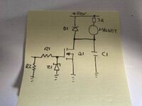
What i think i worked out form the bad pics on pinside is this circuit

nPerV3JlQ3GYeWrP3vOHgQ.jpg

So the additions are R2 and Z1.

If we know the mosfet you are using then we can work out a good value for each of these to add and try. Its not going to hurt to try either.

R2 was added (i think) to make sure the gate voltage is actually 0v when the main controller board turns it off
Z1 was added (i think) to make sure the vGS voltage for the mosfet can never raise higher than the spec'd amount. This shouldn't be possible as the input voltage is only 5v but with noise and static etc possibly it can.

Just my musings early on a wednesday anyway.
 
@myPinballs

Many thanks Jim, I’ve already changed the three control transistors on the 7 segment board, the consign from this board to the magnet board appears good (if my belief of 10% duty hold and 100% duty grab is correct) however I’ll put a scope on it tomorrow/Friday and have a definitive answer on that.

I’ll get the part numbers of the two different mosfets I’ve used, pretty sure one was an OE item from little diode who I use a bit, seems to be proper parts and good selection of obsolete stuff. The later from Andy. I’ll confirm soon.

It all works as it should with the coil unplugged and a lamp plugged in it’s place.

Really appreciate your time and assistance on this rather annoying issue.

All the best,

Chris.

Cool, let me know and we can work out some values for the zener and resistor.

On the bulb test front, what are you using - some sort of old school incandescent bulb? If so then we could be getting to resistive vs inductive here. Magnets are inductive and dont like being turned off once they are on. Large reverse voltages can be caused. A reminder to change D10 on the aux board to, as this would be the main part thats important for a magnet, but not so for a bulb.

Would be interesting to know when the mosfet blows if we get further into this, ie as the main power is applied, or when the main power is turned off Hard to notice but does make a difference

I also have another thought regarding the motor for the moon itself and its connector, but ill leave that for now in case we fix it with the above.
 
@myPinballs

I have taken a look, my findings as follows.....

The 2 mosfets I've used are P20N10L (original spec, from Little Diode) and 24NF10 (from Andy at pinpartsshop).

D10 on the magnet board checked out good, however after no progress it has been replaced with a like for like 1N4004 (from RS) - orientation confirmed correct to print on board and schematics.

The magnet coil when I bought the machine was toast, it was replaced (pinparts) measured 4.3 ohms appeared good, but I wondered about an insulation breakdown, so since replaced it again, now resistance is 4.8 ohms, I stripped the previous one out of interest, there was no evidence of damage to any copper winding insulation, guess it was good.

The 50V coil supply is interesting, it sits at 75V idle, and drops to 68V when operating one coil in test mode (measured Fluke 179 catching minimum voltage, confirmed with scope meter). Iv'e checked the incoming at 245V AC, and the transformer tapping is set to 230V AC (there is no 240V option)

The lamp I used was a 150W rough service incandescent, filament resistance 25 ohms (cold)

The 7 segment board seemed good, however I replaced the three magnet drive transistors in desperation, no change, now checking the consign from the 7 segment board that drives the mosfet, in grab in test mode, it only cycles it in test and doesn't hold permanently on, its 4.86V on for 130mS off for 150mS (measured on a Fluke 123 scopemeter), checking the hold in test, shows the same consign voltage but the 10% duty cycle as expected - good explanation on Sega service bulletin SB80 here....

http://arcarc.xmission.com/Pinball/Stern Service Bulletins/sb/sb80.pdf

If I remove the lamp and reinstate the magnet coil on the first pulse in grab test (hold is okay and works fine) the mosfet fails and locks on, strange as even with 75V at the coil 4.8 ohms (15.6A), the P20N10L at 100V/20A or 24NF10 at 100V/26A should be man enough for the job, there's obviously more to this than I realise!

HELP!

Regards,

Chris.


Yes the problem is not a basic current draw issue as mosfets are rarely failed by this. they have massive current load specs, its normally something else like I mentioned with the Vgs voltage difference or reverse voltage caused when its being shut off or noise and spikes somewhere etc. For example what you could be seeing is the mosfet is ok at turning on for the grab, but doesn't like the breakdown when it is switched off, or something during the shutoff is exceeding the specs. Because the hold cycle isn't creating the same power it not effected in the same way.

I forget how the test works, but is the motor running during this magnet test or not? If so try it with the motor disconnected if possible. There are updates on later games due to the bulbs used on the motors. We can look at this later if the following doesn't help.

So, for the sake of testing and adding these extra parts as noted on the aux board. My suggestion is:

R2 use a 4.7K or 10k 0.25w resistor
Z1 use a 1N4736A - 6.8V 1W zener diode

The Vgs for 20N10 is +-30v, The Vgs threshold is 3v
The Vgs for P20NL10 is +-15v, The Vgs threshold is 1.6v
The Vgs for 24NF10 is +-20v, The Vgs threshold is 3v

So in theory adding these 2 parts should make sure the signal is always off when not specifically turned on and the vGs voltage can never be higher than +6.8v and not negative regardless of any nasty noise or spikes.

If you need some parts I can send you some as I have these anyway.

Caveat - > this is just a theory and isn't guaranteed to solve it as I don't have a game here to look at or test myself. :)
 
Thanks Jim @myPinballs

Iv'e ordered the recommended parts from Farnell, I will post here on the result...

The magnet coil fitted to the moon is a 511-5065 ND, the ND being no diode, I think this is the reason for D10 on the magnet driver board, In your opinion would it be worth adding a further diode or neon to try and reduce any back EMF?

In test mode the moon motor works independently to the magnet, so can only operate any one at a time. Iv'e added the varistor and jumper to the moon motor relay board as per SB81 and not experiencing any issues with the motor and back EMF issue.

Really wish this magnet issue was solved, it's the only thing not working on the machine, although it doesn't effect game play it annoys my ODC terribly!

I greatly appreciate you taking time out to help.


All the best,

Chris.
 
I fitted the zenner diode and resistor as suggested, tried it in hold, it held as usual, tried it in grab, it instantly popped the mosfet as usual :mad:

Ordered some more mosfets and closed the PF down and walked away, I'll maybe get back onto this back end of this week or next week....

Thinking possibly, relocating D10 to near to the coil (flipper coil style) and maybe making up a new board on stripboard..... maybe! Grrrrrrrrr

Regards,

Chris.

damn, annoying to say the least. you could add another diode on the magnet anyway, wont hurt
 
So we need to think about this some more then as to what is happening

you could try an irl540, that’s the default max spec for things mosfet. Or a p40nf10l. Somethings flagging in my head to about ttl drive and non Ttl drive to. Need to check some datasheets

above are 36a to 40a. Maybe a surge at full
Power on start is exceeding the ratings of the other mosfets with the new magnet??

Another idea, add a d600 diode in series with the +70v to the magnet. This was done on the magnet processor boards in games like twister and golden eye. The ones I remade . Need to double check this first but can share a diagram again


@myPinballs

I'll get some IRL540's, that seems to be what is being used by some on threads elsewhere, and readily available from RS.

The d600 diode, is that a TVS diode? What would be your recommendations?

I started looking into the coil I have used, a 511-5065-ND (ND=no diode), the original a 090-5042-01 22AWG, 650 turns, 4.3 ohms, but this seems to be listed as a comparable replacement, thinking about using an old coil with comparable resistance for now, don't really want to hurt the new one in the moon, or am I just importing more unknown variables?

Regards,

Chris.

Just a regular diode P600G or something similar.

https://uk.farnell.com/multicomp-pro/p600gg/rectifier-single-6a-400v-r6/dp/3226331?st=P600G

Put it in series with the coil before fuse probably easiest.
 
Not had much free time recently, so today has been my first opportunity to take a look at this....

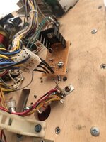
After getting increasingly frustrated and no steps forward, mindful that the moon magnet driver board has now had so many mosfets replaces and not wanting to damage the board, I decided to lash up a board on some Vero board, to include the extra resistor and zener...

51A3CBEF-399B-4FAC-8862-F8985709711D.jpeg

Straight into test mode, hold working nicely, grab.... waiting for mosfet to pop and the coil to lock on, well also worked nicely.

All a bit mystified, the only change is I’m now using an IRL540, other than that all the same, the original board all checked good with a meter and every component, there’s only 4, now 6 with the mod. have been replaced.

So ‘hang in there Odyssey’ never seemed so apt!

Played a few games, very satisfying watching the moon grab the ball and take it away.

@myPinballs Jim, many thanks for your help and guidance, very much appreciated.

I’ll keep my eye out for a decent magnet board, don’t fancy my luck, but you never know.

Thanks everyone 👍😎

Chris.
 
Back
Top Bottom