What's new
Pinball info

Register a free account today to become a member! Once signed in, you'll be able to participate on this site by adding your own topics and posts, as well as connect with other members through your own private inbox!

Any arcade machine experts here?

ronsplooter

Site Supporter
Joined
Jul 21, 2011
Messages
6,469
Location
Nottingham
Alias
Chris
Before I go posting to ukvac are there any vid cab experts on here who could help me diagnose an issue with my Outrun midi?

It’s so much easier to upload photos here and I think they really help with figuring stuff out.
 
Happy to try and help you out Chris if you let us know what the tech problem is? I’m not a mega expert on outrun per say, but I have fixed a fair few differing arcade games, pcbs, monitors etc along with converting many pcbs to run other games
 
Last edited:
Is this guy on here ?


He has done some great videos and seems like he knows his onions.
 
what's your problem is it the pcb,or just a wiring issue?,there is an updated version of the enhanced rom set just been released which is simply amazing
 
Is this guy on here ?


He has done some great videos and seems like he knows his onions.

Yes Luke is on here.
 
So the issue is a dead monitor. Sometime last year I started getting some intermittent electrical crackling noise from the back of the monitor so I assumed the fly back was on the way out. I moved the game to a different spot and the crackling got worse until one day the monitor died. Rest of the game still working, just playing blind.

I sent the monitor chassis off to Gunblade for repair and it came back last week fully fixed and serviced. Reinstalled into the game but the monitor is still dead, no neck glow and no static on screen so I guessed it wasn't getting any high voltage. The chassis is a Hantarex MTC 9000.

Disconnected the monitor power connector shown here:
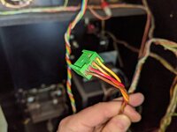
IMG_20200504_171505.jpg

I'm getting the following readings:

Yellow wire 0v
Orange wire 245v
Red wire 0v
Brown wire 0v

I'm told I should be seeing 240v on two of the wires and 110v on the other two. The 110v is to power the monitor and the 240v is for degaussing.

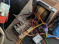
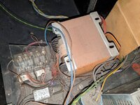
Tracing the wiring back brings me to the fuse board and transformer in the bottom of the cab. All of the fuses test ok out of the game and I get continuity across all 5 fuse holders with the fuses in.
IMG_20200504_171526.jpg

Testing voltages at the fuse board gives:

3A 220v reads 240v
2A 220v reads 240v
5A 13v reads 15v
2A 100v reads 0v
2A 128v reads 0v

So it looks like I've lost a couple of voltages at the fuse board. I've disconnected pretty everything downstream so I can focus on mains coming in, transformer and fuse board and next thing is to check voltages coming off the tranny but I can't believe thats bad as they so rarely go dodgy. Any ideas?

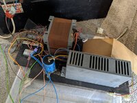
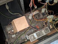
There's a load of other bits and pieces on the power board:
IMG_20200504_171513.jpg

From what I can tell they are:

Big capacitor - for smoothing the DC voltage?
Bridge rectifier - for converting the AC to DC
Small square PCB with 3 connectors - no idea?
What looks like a switching power supply - it seems to only provide 5v and ground so I think this just powers the game PCB?
Weird little board with molded plastic on it that looks like it surrounds some components - no idea other than it gave me a hefty zap once!

Any ideas or advice on any of the above would be appreciated 👍
 
What model of game is it again so we can do some searching for wiring diagrams and power board schematics
 
Outrun midi/cabaret. It's based on Sega System 16 but has an extra 68000 for some of the graphics (I guess the super scaler bits)
 
if you had a spare iso you could power up the monitor with that and check it's working,if gunblade has fixed the chasis,then that would be my way of checking,if you have any other arcade games with hanty chasis,you could use the iso from one of them to test it
 
I've got a ms pac and donkey Kong cabarets but I'm assuming they won't have the right monitor and tbh don't really want to start taking them to bits if I can help it. If the tranny is bad, what are my options?
 
yes as Ronnie says test the voltages off the actual lugs on the iso first,then you will be able to tell if it's faulty or not
 
Ok, so see the attached. I think this is the correct wiring diagram for your cab even though its from the std upright model. Normally cabaret models just use the same internals as the big brother upright.

Now looking at this wiring diagram makes sense as to what you are reporting on fuse locations and the wiring plug for the monitor.

So to give some info on what you posted earlier:

3A 220v reads 240v :Main Power in line fuse, before main line filter
2A 220v reads 240v : Ac feed for fan motor
5A 13v reads 15v : Ac feed for audio amps & coin door (+12v once rectified)
2A 100v reads 0v : Ac feed for solenoid board
2A 128v reads 0v : Ac feed for Monitor

Also your monitor plug has 4 wires because the degaussing coil is also fed directly to it from the main power in., ie 2 for this and 2 for the monitor ac voltage from the transformer.

So, because you've got no 100v or 128v ac i would suspect there is a broken wire on one of the transformer input taps, or a bad connector somewhere here. Its unlikely that both high voltage outputs on a transformer would suddenly stop working.

Does look pretty dirty down in the power supply area of your cab. I'd suggest its time to go through all the connectors and give it all a good clean up to. Take the power supply board out and inspect it where you can see it all properly. Nothing different to pinball maintenance advice.
 

Attachments

  • Out Run Mini Upright wiring.pdf
    1.2 MB · Views: 7
Ok, so as above all I've currently got connected to the power board is main's power and earth. Everything else is disconnected so all I'm hopefully testing is the fuse board, iso transformer and a few connectors. As part of the cleaning process I put all new fuses in but that's it, no wires re-soldered or anything else messed with at this stage.

First I rechecked the voltages at the fuse board using the info from Jim above:

3A 220v reads 240v :Main Power in line fuse, before main line filter - still ok
2A 220v reads 240v : Ac feed for fan motor - still ok although the fan is long gone so I'm guessing this is basically used for nothing
5A 13v reads 15v : Ac feed for audio amps & coin door (+12v once rectified) - this has changed and now reads 0v but I'm thinking this is because I've got other stuff on the power board disconnected?
2A 100v reads 0v : Ac feed for solenoid board - still 0v
2A 128v reads 0v : Ac feed for Monitor - still 0v

Looks like the cleaning hasn't changed anything assuming the lack of 15v is due to my theory above. So now to test the transformer......

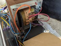
As shown in the pics above, I started with the side of the transformer facing the fuse board which I think is the input side? It's got 4 lugs on it and from top to bottom they read:

Lug 1 (labelled 240) - reads 245v and has 1x brown and 2x orange wires connected to it
Lug 2 (labelled 230) - reads 234v and has no wires connected
Lug 3 (labelled 220) - reads 224v and has no wires connected
Lug 4 (labelled 0) - reads 0v and has 1x blue and 2x grey wires connected

So this looks ok to me if my assumption is correct re: this being the input, it's wired for 240v and Gnd.

Looking at the other side of the transformer which would be the output. It's got 6 lugs on it and from top to bottom they read:

Lug 1 (labelled 0-11) - reads 0v and has 1x thick orange wire connected
Lug 2 (labelled 0-11) - reads 0v and has 1x thick red wire connected
Lug 3 (labelled 0-128) - reads 0v and has 1x thin red wire connected
Lug 4 (labelled 0-128) - reads 0v and has 1x thin brown wire connected
Lug 5 (labelled 0-100) - reads 0v and has 1x thick blue wire connected
Lug 6 (labelled 0-100) - reads 0v and has 1x thick purple wire connected

Based on the above I'm getting no voltages out of the iso transformer at all so does that point the finger at the 240v input side? Maybe a broken wire in the tranny? I need to take a closer look at that side I think but would rewiring it to the 230v lug cause any issues, just to see if that produces some voltages?
 
I take it there are no door interlock switches killing mains to cab?

There is Ronnie and I've got it pulled out for testing. The mains coming in reads good through the fuse and line filter :thumbs:
 
Grant over on UKVAC has pointed out that I might not be measuring the voltage right on the output lugs :rolleyes: I was connecting one lead to earth and then the other on each lug whereas it sounds like I should have one lead on the 0 lug and one on the value lug. So for example, to measure the 128v output I need a lead on lug 3 and a lead on lug 4. Will retest and report back :thumbs:
 
Grant over on UKVAC has pointed out that I might not be measuring the voltage right on the output lugs :rolleyes: I was connecting one lead to earth and then the other on each lug whereas it sounds like I should have one lead on the 0 lug and one on the value lug. So for example, to measure the 128v output I need a lead on lug 3 and a lead on lug 4. Will retest and report back :thumbs:

was just about to say that but you got there! [emoji2]


Sent from my iPhone using Tapatalk
 
Grant over on UKVAC has pointed out that I might not be measuring the voltage right on the output lugs :rolleyes: I was connecting one lead to earth and then the other on each lug whereas it sounds like I should have one lead on the 0 lug and one on the value lug. So for example, to measure the 128v output I need a lead on lug 3 and a lead on lug 4. Will retest and report back :thumbs:

Ah, easy mistake if you are used to dc volt testing. Also make sure your dvm is set to ac volts. So yes measure using both taps for each ac voltage. Also be careful with not touching the bare end probes to as we are talking about high ac voltages here
 
Some good news! It looks like the transformer is ok.

Measured lug to lug I get the following:

Lug 1-2 (0-11) reads 11v
Lug 3-4 (0-128) reads 132v
Lug 5-6 (0-100) reads 106v

Now I need to start tracing wires away from the transformer and see where I’m losing voltage.
 
Some good news! It looks like the transformer is ok.

Measured lug to lug I get the following:

Lug 1-2 (0-11) reads 11v
Lug 3-4 (0-128) reads 132v
Lug 5-6 (0-100) reads 106v

Now I need to start tracing wires away from the transformer and see where I’m losing voltage.

good news. Use the wiring diagram to locate those connectors in between the transformer output and the monitor input.
 
Back
Top Bottom