What's new
Pinball info

Register a free account today to become a member! Once signed in, you'll be able to participate on this site by adding your own topics and posts, as well as connect with other members through your own private inbox!

Afterglow PCBWay build, in progress, looking for feedback

Ashram56

Registered
Joined
Nov 10, 2020
Messages
76
Location
France
@caponian, @stumblor,

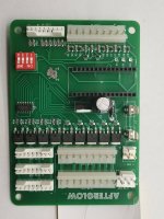
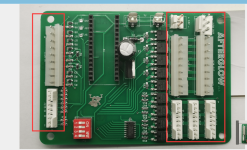
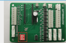
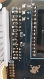
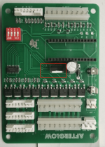
I received the following assembly pictures from PCBWay on my Afterglow order (regular Afterglow, not AGGI). This is common usage with PCBWay they assemble first one unit before moving ahead with the rest of the assembly.

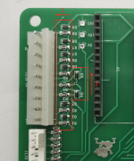
Could you please check if you see anything odd (especially diode orientation) ? I checked according to Afterglow github and did not see anything.

The big capacitor (C1) seems to interfere slightly with Arduino Nano connector though, thoughts ?

Regards
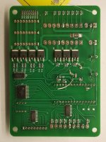

IMG_20201208_181453.jpgIMG_20201208_181502.jpg麻烦确认一下坐子方向.png麻烦确认一下开关方向.png
 
Last edited:
I presume you mean Nano not Uno. I would add orientation on silkscreen for Nano.

David
 
C1 will be fine, and the big diode is okay. IC orientation all looks fine. I just need to check the power input J3 because from memory it's reversed, but I could be wrong (and confusing with an earlier iteration). Also need to check smaller diodes. I have some working assembled versions handy I will check and send some closeups through.
 
@stumblor, have you been able to confirm the orientation of J3 and the diodes ? I checked the orientation off the connectors on the github and unless I missed something they seemed correct
 
@Ashram56 Just checked

J3 all good
Diodes - I can't 100% see in the photo, but they look right. To confirm, all the 1s should be pointing left, and both 2s should be pointing up.

1608042380221.png

To compare with mine:

1608042447404.png
 
Received the Afterglow boards (regular, not GI), on for testing now

A few questions though @stumblor and @caponian :
- The games.json file does not seem to have all tested machines (even after online update), is there an alternate repository with additional games ? Specifically looking right now for CFTBL (since it's my test unit) and a "Flinstones" (for a friend).
- Do you need to edit manually using Notepad++ the JSON file to change the lamps names ?
- When I load a default game, looks like the default values are all set to zero. Looking at the JSON file this seems logical, is there a default value (non zero) used by the firmware at first boot, or do we absolutely need to adjust values ?

Thanks !
 
Do you actually need to set up the game in config?

My BoP is running without me setting anything up.

I assumed it ran what it was given as input and ran it at max brightness.
 
@stumblor, @caponian, one additionnal question: did you mount a 5V regulator, and if so which one ? I'm a little bit confused, as apparently power needs to be provided by 18V + fuse + regulator, but at the same time the 5V signal is connected to J135 pin 6

With regards to software configuration, I found my answer, indeed there are default settings set (140 glow, 7 brightness) for all lamps, you can finetune as you want depending on the LED you are using.

[EDIT] I take it back, the 5V signal is used to reference pullup resistors, I checked the schematics. So I do need to add this 5V regulators :)
I kind of wonder where ledocd takes it's power from, I'll have to check
 
Last edited:
If I can package this OSX version of the config tool, I'll add Hurricane and BOP to the game list.
 
Are there any updates to the BOM which I should take to the github page? What was missing? I'm trying to tidy up the wiki pages and other content.
 
It would be good to add the 5V regulator directly in the BOM itself, it's currently not in the BOM, and has only a reference to it in the Wiki instructions (so I missed it). Also, there is no component reference for this regulator on the PCB itself, so I'm unsure how a PCB manufacturer/assembly would know where to solder it (it was already difficult to make them understand that you need two fuse holders for one fuse reference, they just did not seem to get it).

Also, on the PCB design itself, is it possible to indicate where to "not" solder the pins that have to be removed on the connectors (since these connectors are keyed) ?
 
I'm not sure I know what you mean regarding BOM really. :) Sorry!!

But on the code,...

I found that I needed to change the baud rate to 115200 to get AVRDUDE working for one of the Nanos I had. Dunno if someone maybe had the wrong thing installed?! I need to test that again
Could AVRDUDE be packaged with the installer somehow when deployed?
There was a depreciated font style type, setForeground is requireed now instead of whats there. mainWindow line 381
I have added 2 games to the games.json .. if I create a local file, and I update the file (world icon), it overwrites my local file. Maybe that needs a warning, or an update to the json file rather than an overwrite?
Updated games list with Hurricane & BoP - https://www.dropbox.com/t/qDsAQDcn6x1UPuCo

I am not sure if its my version only, but if I change the Glow rate in one game, it seems to be reflected across ALL games.
Thinking about this, seems logical. The Afterglow config is configuring a single board in a single game.
Had a few ideas on multi game, cloud saves ;-)
 
Last edited:
Sorry, the BOM question was more for @Ashram56 and @stumblor to answer as they have prepared the production.

As for the code:
  • For Windows the avrdude binary is deployed together with the application
  • Maybe the baud rate for the update needs to be configurable. To keep the interface simple I may just add the option to configure a few things in a text file. Though I am still surprised that your Arduino used a different baud rate.
  • If you have code changes you can create a pull request on github. Or if you're not familiar with git then just send me the changes directly. I will update the code.
  • The game list is meant to be updated on github. So when you add a game you (github pull request) or me (you send me the file) updates the file. Then everybody gets the code. There was also some pinball iphone app that seems to have the matrix for all games. Maybe if we ask them nicely...
  • Yes, the game list is just there to make it easier for you to identify your LEDs. But it's a single game configuration tool.
 
It would be good to add the 5V regulator directly in the BOM itself, it's currently not in the BOM, and has only a reference to it in the Wiki instructions (so I missed it). Also, there is no component reference for this regulator on the PCB itself, so I'm unsure how a PCB manufacturer/assembly would know where to solder it (it was already difficult to make them understand that you need two fuse holders for one fuse reference, they just did not seem to get it).

Also, on the PCB design itself, is it possible to indicate where to "not" solder the pins that have to be removed on the connectors (since these connectors are keyed) ?

Do you mean this page in the wiki?

https://github.com/bitfieldlabs/afterglow/wiki/Regulating-5V

From what I understand (and Christoph @caponian might help me out here) this page is more about how to ensure that voltage doesn't drop below a certain level (called the 'brown out') as otherwise the Arduino can run into problems. This is circumvented by flashing the bootloader to use a 4.7V brown out detection, which is what I did for all the nanos when I did my build (PM me for instructions if unsure, it can be a bit fiddly).

The 5V regulator is mentioned on the v1.3 BOM - its at U3 (LM7805). Its this fella:

1611779207166.png
 
With regards to the pins, honestly it's just easier to snip them once you have the boards. Buy a thimble (old school!) and hold the pin down with it when you snip otherwise it will 100% ping up into your eye.

You don't want to look like this 😉
 
Ah on the regulator, how did I miss this... And I did check the netlist on the PCB, yet for some reason I did not see that U3 was actually also used to generate 5V. Here's the funny part, I just bought 20 of DC-DC converters to fit on the right footprint :) Silly me.
So I need to build a custom bootloader and flash it using another Arduino. Funny enough my Nano clones from China did not have the bootloader installed, so I precisely had to go through this exercise (except I used a stock ISP).

Getting there...

No probs!

So I use the MiniCore bootloader (https://github.com/MCUdude/MiniCore) which loads super quick and doesn't have a lot of fluff. Some of my projects rely on super quick boot time so this suits me well. I've had great success with the Pololu USB AVR programmer , if you ever wanted to use a dedicated one rather than an Arduino:

https://www.amazon.co.uk/Pololu-USB...lolu+USB+AVR+Programmer&qid=1611823449&sr=8-1

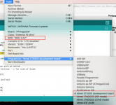
MiniCore has great features within the Arduino UI, which allows you to select things like brownout direct from the Tools menu, rather than having to muck about with avrdude command line args.


1611823683192.png

MiniCore has great support within vscode/platformio also.
 
@stumblor, I need a little bit of clarifications here.

Currently I'm flashing my bootloader on Nano using an Arduino as a programming device, as outlined here: How to Upload Bootloader to Any Arduino ! : 5 Steps - Instructables
So I flash a working Nano with the ArduinoISP code, define "Arduino as programmer", connect the other arduino Nano with the wiring indicated, and proceed to burn the bootloader

Where I'm confused is the command line in the github:
avrdude -v -V -patmega328p -cavrisp -b19200 -P/dev/ttyUSB0 -D -F -Uefuse:w:0xfc:m

The command line parameter -cavrisp indicates to me it's not using the "Arduino as programmer", unless I'm mistaken ?

That said Minicore seems a good option, and it's documented, so I'll take a look at it
 
I never had any luck with the command line, but yes you're right, the -cavrisp corresponds to this programmer:

1611845730411.png

I'm no expert, but give -cstk500v1 a go. I think that and the arduino share the same programmer spec.

Otherwise just use MiniCore :-/
 
avrisp should be the "Atmel AVR ISP".

Works fine for me on the command line with an Arduino Nano as ISP.
 
So, Command line works, I had to adjust it (Windows based), I replaced the -C parameter with stk500v1 (extracted the info from the log file when burning a regular bootloader using ArduinoISP). I was able to flash and read back the fuse
Minicore for some reason I had failures, I could flash but when using the Afterglow windows tool I had failures (it could not update the Arduino)

Anyway, I'm good to go, for reference here's the command line I used (using an Arduino as the programmer, no direct connection of course), after flashing a stock Arduino bootloader (not minicore):

avrdude -C"C:\Program Files (x86)\Arduino\hardware\tools\avr\etc\avrdude.conf" -v -patmega328p -cstk500v1 -b19200 -Pcom4 -D -F -Uefuse:w:0xfc:m

(assuming default path for Arduino IDE)

and to read back:
avrdude -C"C:\Program Files (x86)\Arduino\hardware\tools\avr\etc\avrdude.conf" -v -patmega328p -cstk500v1 -b19200 -Pcom4 -D -F -Uefuse:r:-:i
 
With regards to power supply, does Afterglow absolutely require 18V ? I checked WPC schematics, and could not find a connector that expose it. I must admit I'm not a big fan of the alligator clip :)

So LEDOCD draws power directly from the insert matrix ?

Alternatively, adding a bridge rectifier and piggy back on the sound board J501 connector which has a 18VAC input could be an option, but it requires a little bit of space on the PCB.
 
It would be nice to negate the croc clip on the 18v TP for sure :)
 
There are options to draw the 18V from the columns directly. However, there are (or at least might be) some drawbacks:
  • Larger PCB, larger BOM
  • Power/heat dissipation over diodes
  • Board is only powered when columns are driven (need to check what the pinball machine does in test/config mode)
  • Capacitor needs to be able to bridge the gaps when no column is driven (anti ghosting ROMs)
  • Original column drivers must all work properly. They will still be stressed.
  • The ground still needs to be connected to the PDB.
Personally, I prefer the separate connection of the 18V and I would definitively keep that connector on the board. Also, I don't really mind connecting to the test point, there are probably also alternatives to the alligator clip.
 
Anyone would know the Manufacturer/PN of that test point ? I could try finding a female connector for it
 
Back
Top Bottom