What's new
Pinball info

Register a free account today to become a member! Once signed in, you'll be able to participate on this site by adding your own topics and posts, as well as connect with other members through your own private inbox!

Advice on fault finding Red Hot Firebirds NSM machine

Jacksonpuk

Registered
Joined
May 26, 2024
Messages
11
Location
Lincoln
Hi
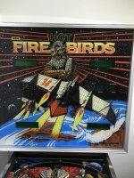
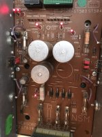
I have a problem with all the side flippers on this machine. It is fundamentally a Gottlieb machine on the playfield with more digital NSM German electronics grafted on the upper scoring displays. (Manufactured 1985) Playfield hardware seems very similar to the Gottlieb Alien Star machine.
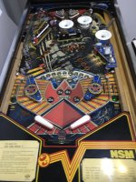
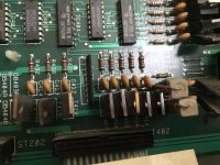
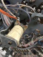
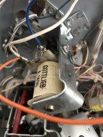
The flippers were working but changed out the rubber rings on one and fitted a ring that was too small. This caused the firing switches to be pressed permanently which caused the coil to overheat. The power was removed fairly quickly but after this the all the side flippers do not work. The lights and switches associated with these flippers all appear to operate ok.
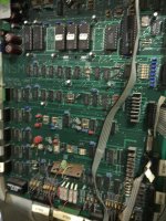
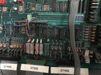
Any suggestions on what and how to test greatly received. I do have reasonable electrical knowledge and limited electronic understanding. Can use meters and soldering equipment ok.
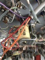
 

Attachments

  • CE38B3FF-3F78-4092-AA45-550AF016E3DD.jpeg
    CE38B3FF-3F78-4092-AA45-550AF016E3DD.jpeg
    155.8 KB · Views: 22
  • 93A56F3E-0089-47EC-BDCB-AED2ABDD05F7.jpeg
    93A56F3E-0089-47EC-BDCB-AED2ABDD05F7.jpeg
    135.7 KB · Views: 27
  • 3EDDD384-6681-470D-AD82-B9F578BF1D25.jpeg
    3EDDD384-6681-470D-AD82-B9F578BF1D25.jpeg
    165 KB · Views: 22
When you say side flippers, it looks to me like you're talking about a slingshot kickers.

If you haven't already, download the manual and schematics from ipdb. Print them out. If you understand German then no problem, if you don't I would use google translate (or another translation programme) on a smart phone to convert to English.

If you're lucky then you've just taken out a fuse (as none of them are working), if you're unlucky you've destroyed a coil, a drive transistor and fuse.

With the power off, first check F504 and F505 - pull them out of the holder and test their continuity with a meter. Replace the blown fuse (8A slow blow). When you apply power, if the coil locks on again then switch off and you'll need to replace the coil and drive transistor. If the coil doesn't lock on again then you can test with out the rubber fitted by activating the switch and see if the kicker fires properly, if it locks on the switch off and replace coil and drive transistor. Page 8/23 on the schematics shows F504 and F505 on the left - LED502 - 24/48v will probably not be lit when power is on. If any of the other LEDs are not lit then that would indicate that there is a problem with another fuse.

Good luck!
Many thanks for your advice. I will try your tests as soon as I can. Sorry about the terminology description mix up.
 
Many thanks for your advice. I will try your tests as soon as I can. Sorry about the terminology description mix up.
4A25CB47-D5F6-4C5A-8DAF-0691C92FAA5F.jpeg
Hi
Have tested all fuses. All ok. Have made video which I believe shows the firing switches behind the rubber ring working?

Any further ideas gratefully received

Regards
Paul
 

Attachments

  • 89D17414-4995-4136-8E1C-9A01200C22ED.jpeg
    89D17414-4995-4136-8E1C-9A01200C22ED.jpeg
    182.7 KB · Views: 7
  • 73921715518__72BBFA91-9304-4E72-BC00-7D398CD489CA.MOV
    3.3 MB
You've proved that the switches are working and that the solenoids are not (which is why I think it's a fuse).

Did you remove the fuses from the holders and test them using the continuity/beep test with a meter?

Do all the red LEDs on the power board light up to show correct voltage?
 
Hi
Not sure if you can see in this photo but all six Red LEDs are illuminated. I took each fuse out and did a buzz meter continuity test. All seem good to me.
 

Attachments

  • 9B4F7EF7-8B28-4649-83E4-4EAC4BF34EFD.jpeg
    9B4F7EF7-8B28-4649-83E4-4EAC4BF34EFD.jpeg
    101.8 KB · Views: 10
OK, so you have the correct voltages. Next, do you have the correct number of balls in the trough before pressing start on a game? If so, does the game kick the ball out of the trough in to the shooter lane?
 
Hi
Yes there appears to be two balls in the machine and the first ball presents itself automatically as it should.
 
Hi
As a bit of extra info I believe all other functionality on the machine works as it should. It is just the three side kickers that do not operate.
 
Have you measured for power being present at the coils?
EDIT: Looking at the schematics, it seems that this one switches power instead of ground. So no use measuring at the coils. There are bridges to configure this, if DB403B is in it is indeed switching power. Anyway, ground should be daisy chained from coil to coil, check if that is broken somewhere, you can measure connectivity from the coils to ground to establish. Drivers are T413-415 otherwise, that is the next thing to check.
 
Last edited:
Have you measured for power being present at the coils?
EDIT: Looking at the schematics, it seems that this one switches power instead of ground. So no use measuring at the coils. There are bridges to configure this, if DB403B is in it is indeed switching power. Anyway, ground should be daisy chained from coil to coil, check if that is broken somewhere, you can measure connectivity from the coils to ground to establish. Drivers are T413-415 otherwise, that is the next thing to check.
Hi
Tried attaching a voltmeter across each coil and manually pressing the switches but nothing detected.
How can I go about testing the driver transistors which I have located on the main pcb ?

The common connection all seems good to me.
 
Hi
They are BDT62A Darlington in TO-22 package.
I only have a multimeter available atm. Could obtain a different test meter if required.
 

Attachments

  • 44498593-C273-4BEC-8BA9-A68D0AF05508.jpeg
    44498593-C273-4BEC-8BA9-A68D0AF05508.jpeg
    159.4 KB · Views: 8
  • 7FADD060-69B2-4046-8A1A-5DB6AE84E623.jpeg
    7FADD060-69B2-4046-8A1A-5DB6AE84E623.jpeg
    90.6 KB · Views: 8
  • F35EEE77-5FFD-4234-8C88-5603FD73CCE8.jpeg
    F35EEE77-5FFD-4234-8C88-5603FD73CCE8.jpeg
    98.3 KB · Views: 5
  • 633D55C4-A662-4B51-B697-F93EF09914E0.jpeg
    633D55C4-A662-4B51-B697-F93EF09914E0.jpeg
    101.9 KB · Views: 8
With the game switched off - put your meter on to ohms and measure each of the A-1496 solenoids/coils in your pictures. They should each read 3 ohms, if they don't then the problem could be with the coil or diode. Each of these are controlled a transistor and if the coil is faulty then the transistors will most likely need replacing at the same time. Failing that then you may have killed IC404 which controls the transistors - T415 (top Sling), T414 (Left Sling) and T413 (Right Sling).
 
Once you have followed @Moonraker 's suggestion, with machine on measure the base of the transistors, they should be pulled up to 48V. Momentarily ground the base, this should fire the coil if the transistor is good. If that works, IC404 is probably shot.
 
With the game switched off - put your meter on to ohms and measure each of the A-1496 solenoids/coils in your pictures. They should each read 3 ohms, if they don't then the problem could be with the coil or diode. Each of these are controlled a transistor and if the coil is faulty then the transistors will most likely need replacing at the same time. Failing that then you may have killed IC404 which controls the transistors - T415 (top Sling), T414 (Left Sling) and T413 (Right Sling).
All the solenoids read 3 ohms.
Given the only one solenoid was in operation when the original fault was caused would not the IC404 be the most likely candidate as this I assume is common to all three solenoids?
 
Yes, but it also operates other coils which work. Try operating the transistors next, if those work it probably is the driver. With a logic tester or scope you could follow the signals.
 
OK, IC 404 or 403 plus a few transistors. Coil just locked on after a while? A scope or logic tester would be hlepful to check the drive at the transistor base.
 
Right, I have ordered myself a logic probe and I am going to make the problem coils isolatable to avoid further burn outs (I hope!)
 
You can simply desolder them while you're debugging the driver situation. You could simply measure the base of the transistors in the interim to see if they are constantly pulled low - if that is the case the transistor and coil will fry.
 
Back
Top Bottom