What's new
Pinball info

Register a free account today to become a member! Once signed in, you'll be able to participate on this site by adding your own topics and posts, as well as connect with other members through your own private inbox!

A Dead Diner - Sys11 board repair

David_Vi

Site Supporter
5Years
Joined
Sep 3, 2019
Messages
4,005
Location
Sudbury
Claire got her dream pin today, out of nowhere, when we woke up we didn't expect a Diner to enter our life! (see her wanted thread for info).

I only just have a basic understanding of wpc-89, S and 95 and all my games have arrived working.
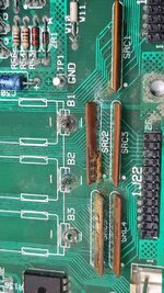
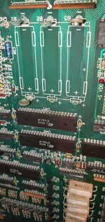
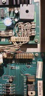
We knew it had board damage so it's no surprise but it's out of my area of expertise.

What are our options for board repair?
Is it worth getting a new or reconditioned board?

20220307_181252.jpg20220307_181319.jpg20220307_172735.jpg20220307_172636.jpg
20220307_182534.jpg
 

Attachments

  • 20220307_172630.jpg
    20220307_172630.jpg
    100.1 KB · Views: 11
Last edited:
Hopefully its not to far gone and can be fixed. I know when I had similar issues with bodged previous repairs on an mpu board, I was advised that it can actually make any further attempt to rectify the problem harder. Jim will know for sure.
 
I would try to get it repaired if possible. My SOF had a Rottendog MPU replacement and that had its own issues - wouldn't recommend, especially at £400 a pop! Original replacements are quite rare to find.
 
Took board out and noticed one of the roms wasn't in fully, I doubt that was the cause of the issue but still I'll pop it back in and take a chance 😆

I would try to get it repaired if possible. My SOF had a Rottendog MPU replacement and that had its own issues - wouldn't recommend, especially at £400 a pop! Original replacements are quite rare to find.

Yes James warned us Rottendog ones aren't great.

i’d replace with much thinner jumper wires, those are far too thick.

I'll give that a go👍
I can't tell if the long one was supposed to attach to a pin in the middle or they just used two short wires for it
 
Took board out and noticed one of the roms wasn't in fully, I doubt that was the cause of the issue but still I'll pop it back in and take a chance 😆


Yes James warned us Rottendog ones aren't great.


I'll give that a go👍
I can't tell if the long one was supposed to attach to a pin in the middle or they just used two short wires for it
if it was attached, then maybe you can see where it was attached, seems likely - but best thing to do is dig out schematics and see where it seems to be going and check on the schematic that those two points should be connected. Now that IS something you can do yourself.
 
Was testing other boards and seeing if any issues further back.

On this connector on the power supply board I don't get anything from grey white. manual says it's 19.4v AC CT common.
No idea what that means and if it's supposed to be zero. The other pins are showing correct voltages.
 

Attachments

  • 20220307_235331.jpg
    20220307_235331.jpg
    91.6 KB · Views: 11
Take lots of pictures, then unplug everything apart from power and work on getting the status leds all correct, once the main mpu boots start plugging stuff back in. Also check board is receiving all the correct voltages / fuses all ok.
 
Was testing other boards and seeing if any issues further back.

On this connector on the power supply board I don't get anything from grey white. manual says it's 19.4v AC CT common.
No idea what that means and if it's supposed to be zero. The other pins are showing correct voltages.
You did set your meter to ṽ ?
 
Took board out and noticed one of the roms wasn't in fully, I doubt that was the cause of the issue but still I'll pop it back in and take a chance 😆


Yes James warned us Rottendog ones aren't great.


I'll give that a go👍
I can't tell if the long one was supposed to attach to a pin in the middle or they just used two short wires for it

If you want me to look at the board, no problem, but PLEASE do not attempt to do anything else on the board. STOP, take it out of the game , pack it up and post it here

Many issues for these old board are caused by bad previous repair attempts, or at least it makes the repair harder because all the bodges have to be undone first.

This board does have old acid damage to, so it need inspecting closer with x20 glasses on and a logic probe to find the route cause of the issues.

:)
 
Last edited:
If you want me to look at the board, no problem, but PLEASE do not attempt to do anything else on the board. STOP, take it out of the game , pack it up and post it here

Many issues for these old board are caused by bad previous repair attempts, or at least it makes the repair harder because all the bodges have to be undone first.

This board does have old acid damage to, so it need inspecting closer with x20 glasses on and a logic probe to find the route cause of the issues.

:)

It's been packed up since yesterday 🙂 I just tried to put the jumper lead back and see if anything changed nothing else👍
 
Was testing other boards and seeing if any issues further back.

On this connector on the power supply board I don't get anything from grey white. manual says it's 19.4v AC CT common.
No idea what that means and if it's supposed to be zero. The other pins are showing correct voltages.

CT means Centre Tap for the AC input. This circuit is the input that is used to generate the +12vDC and the -12vDC from the bridge rectifier.

If you measure Grey and Grey/White or Grey/Green and Grey/White you should get roughly 9.7 VAC (Mulitmeter on Ac voltage setting)
 
Somebody took the welding torch to that one for sure. Can have a look at it for you if you can’t figure it out, am round M25 in Bourne End.
 
CT means Centre Tap for the AC input. This circuit is the input that is used to generate the +12vDC and the -12vDC from the bridge rectifier.

If you measure Grey and Grey/White or Grey/Green and Grey/White you should get roughly 9.7 VAC (Mulitmeter on Ac voltage setting)

It comes from the transformer yeah?
I tried testing from the connector in the bottom of the cabinet when disconnected but
Can I confirm that I clip one probe to ground and use the other to test? Just incase I'm going mad here.

Is there somewhere else on the power board to test it's getting the correct voltages out as for some reason that connector is being inconsistent with my multimeter.

Somebody took the welding torch to that one for sure. Can have a look at it for you if you can’t figure it out, am round M25 in Bourne End.

Cheers for the offer 👍 Jim is going to take it .
 
It would be as Jim mentioned in his post above.
Oh measure between them🙄🤦‍♂️

Sorry , still learning and never had to do that. Always used ground when checking voltage so thought it would be the same
 
yes £300+ for original board, and even then its likely to have suffered alkaline-battery damage

this is the worst damaged sys11 board that I've seen recently, and this is North of the battery site!!

cheers Bob

2021-09-02-15-28-24-jpg.162981
 

Attachments

  • 2021-09-02 15.28.24.jpg
    2021-09-02 15.28.24.jpg
    141.5 KB · Views: 140
Back
Top Bottom