What's new
Pinball info

Register a free account today to become a member! Once signed in, you'll be able to participate on this site by adding your own topics and posts, as well as connect with other members through your own private inbox!

60s EM ttansformer advice

kev a

Site Supporter
5Years
Joined
Jun 4, 2019
Messages
753
Location
Guernsey
Hi all picked up a couple of EMs this week

1963 Williams Swing Time and a Gottlieb Surf side, unfortunitly missing the head.

The Swing time looks to be complete but had had the transformer removed at some point.

I have pinched the transformer from the Gottlieb for the time being, its only 115v so has a seperate transformer for 230v - 115v

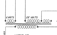
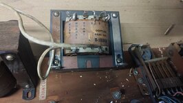
So far ive got 115v comming in to the bottom lugs and testing the voltages at the top im getting strange readings that don't seem correct. Im assuming the lug on the right marked 0 is common

With the multimeter set to AC and one lead on 0 im getting these results on the other lugs....

5 5v
6 6v
Start 30v
Normal 15v
High tap 20v

Think I should be getting something around 24v ish on high and normal?

Im assuming either the transformer is bad or more likley im doing something wrong :/
20221027_104913.jpg
 
Ok, read the pinside post and I sorta get it.

Post no 6 says the start is the centre for reference and measuring mine im getting 29v between normal and start, with no load that seems about right.

The guy I got them from was clearing out his parents stuff. He's checked everywhere he can think of for the head, but there's a very small chance it will turn up somewhere.

In a couple of weeks if it hasn't turned up I will start stripping it and your welcome to the plastics and anything else, other than the transformers I pinched it looks complete
 
Start to Normal or Start to High should give you the Hv 50V or so that you need. The "0" lug on rhs is only for the low voltage 5 or 6 v lighting circuit

The High was included for situations where the mains voltage was a vit lower than it should be.
 
Start to Normal or Start to High should give you the Hv 50V or so that you need. The "0" lug on rhs is only for the low voltage 5 or 6 v lighting circuit

The High was included for situations where the mains voltage was a vit lower than it should be.
Bargain thanks dude, wired it up that and got flippers pop bumpers and some scoring, although its constantly stuck in game, with no bonus countdown or end of ball, going to clean the jones plugs and go from there.

Thanks guys 😀
 
If you manually step up and step down the ball count unit (almost certainly in the backbox) does it move freely? If the ball count unit won't move the game will be endless.

Often with games that have been stored for some time old grease solidifies (or WD40 turns sticky) and the stepper units jam up. In that case the affected unit needs to be dismantled and cleaned with isopropyl. On reassembly only the tiniest wipe of Teflon lube should be added - pinballs need very little lubrication, ( and definitely no WD40!)
 
Thanks guys!

Sorry for all the q's its very new to me this EM stuff, more used to a service menu 😀

Have some serious reading to do I think. Will have a look for the ball count, I think I may have already seen it in the backbox. If its the part im thinking of it didn't increment forward on the cog when I manually moved the coil plunger, like it was clogged up.
 
Thanks for the advice guys, managed to clean up the ball count and advance unit, also cleaned up the switch contacts that register the score wheels are at 0 and found a broken wire on the jones plug for that switch.

As it stands the coin up button now activates the start/reset relays the scores return to 0000 and the ball count advances to 5, one of the switches in the ball trough decreases by 1 each time the ball drains.
So, it seems to be starting and ending games correctly.

I'm left with one issue, although it's now playable and it's probably not an issue in a home environment anyway.....

The with the kick switch in the normal position i.e engaging the lock coil, the coin up function doesn't do anything, jamming the switch closed disengages the lock coil and everything functions as normal, however with it like this even after a game over the flippers still function and the ball still gets served.

I'm guessing there should be something in the start relay that triggers the lock coil to release and something in the game over relay that re engages or something, opening and closing the 24v rail.

But despite looking all over, I can't see anything obviously broken or wrong.
 
Not sure which switch you mean when you say "kick" - do you mean the anticheat bounce switch?

Do you have the schematic?
If not you can download it here:

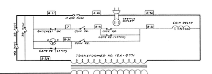
As I read it the game/game over function is controlled by a latch relay
With the anticheat switch closed operating the coin switch will energise the coin relay through either of a switch on the lock relay and a switch on the game relay - I would check you are getting current through this switch as it probably ids the alternate path once the lock relay is energised.
The game relay is energised by a switch on the coin relay when the ball count is at the minimum position and motor switch "index B" is closed
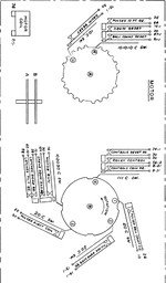
The game over relay is energised directly through a switch on itself when the ball count unit reaches its lowest position - I'm a bit puzzled here because the diagram doesn't show a motor switch in this circuit, but the motor diagram shows a switch (at the bottom) which "pulses game over relay" - I don't know if there is an error in the diagram or I'm missing something

Hope this helps
David


1667216937839.png1667217210309.png
1667218657136.png
 
Thanks for that, I had had a look on IPDB but didn't see the schematic, think that will be a great help 😀

Could be an anti-cheat switch I will try and get a picture, it's a plastic rod that when held upwards closes a switch which de energises the lock coil.

On another note I haven't heard anything from the seller about the missing head, going to make a start stripping stuff soon as its getting in the way in the garage, do you wanna let me know a list of any Surf Side bits your after and I will make a start stripping them.
 
That switch you refer to sounds like the "kick-off" switch - although that is normally closed and opens when you hit the underside of the cabinet (used on this era of games to turn the game off instead of an on-off switch)
 
Yeah, that sounds like the one, when its sitting on the floor of the game the lock relay is energised, which I believe is the default game over state, although nothing seems to trigger the lock coil to disengage when the coin relay gets triggered.

I can jam the kick off switch up, but it falls down on its own disabling all the 24v although the 6v remains.
 
The lock relay should be energised all the time the game is alive (ie lit up), in game and in game over

The kick off switch should be normally closed - when it opens it breaks the circuit to the lock relay and switches off the game

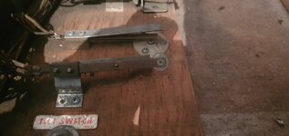
Your kick off switch should have the large blade on the top - this is lifted by the plastic rod if you hit the underside of the game - that opens the contacts and turns off the game - photo is from my 1963 Wms Skill Pool

1667230184326.jpeg
 
It's possible someone in the past might have routed the 6v around the lock relay
In the past games didn't light up on first switch on until you put a coin in (or on slightly later games pressed the left flipper button)
Because people were reluctant to put a coin in an apparently dead game some operators did some rewiring to make sure some of the lights were always on when the game was stood ready to play
 
Right, that's making sense, that looks just like my kick off switch, except with mine in that position the 24v is disabled. Mine appears to be backwards in some way, like there should be 24v coming into that kick off switch and activating the lock coil?
 
Cool, well defo sounds like there something amiss there, so that gives me something to go on thanks for all your help dude :thumbs:
 
Back
Top Bottom